


221
CHAPTER 10 UART
●
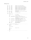
Coding example
PDR4 EQU 000EH ; Address of the port data register
DDR4 EQU 000FH ; Address of the port direction register
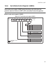
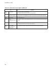
SMC1 EQU 0020H ; Address of the serial mode control register 1
SRC EQU 0021H ; Address of the serial rate control register
SSD EQU 0022H ; Address of the serial status and data register
SIDR EQU 0023H ; Address of the serial input data register
SODR EQU 0023H ; Address of the serial output data register
SMC2 EQU 0024H ; Address of the serial mode control register 2
PSEN EQU SMC2:5 ; Define the baud rate generator operation
; start/stop bit
ILR2 EQU 007DH ; Address of the interrupt level setting register
INT_V DSEG ABS ; [DATA SEGMENT]
ORG 0FFF2H
IRQ4 DW WARI ; Set interrupt vector.
INT_V ENDS
;----------Main program-----------------------------------------------------------
CSEG ; [CODE SEGMENT]
:
CLRI ; Disable interrupts.
MOV ILR2,#11111101B ; Set interrupt level (level 1).
MOV SMC1,#01011011B ; Non-parity, 1 stop bit, operating mode 1,
asynchronous, clock output enabled, serial data
output enabled.
MOV SRC,#00010100B ; Proprietary baud rate generator selected.
Set the baud rate at 150 baud.
MOV SSD,#00101000B ; Disable transmit interrupt request, enable
receive interrupt request.
MOV SMC2,#00000011B ; Stop UART operation, select UART function and
select the input clock divider of 1/65.
MOV SODR,#13H ; Write transmit data (13H).
SETB PSEN ; Start UART operation.
SETI ; Enable interrupts.
:
;----------Interrupt processing routine-------------------------------------------
WARI PUSHW A ; Save A and T.
XCHW A,T
PUSHW A
:
User processing
:
POPW A ; Restore A and T.
XCHW A,T
POPW A
RETI
ENDS
;---------------------------------------------------------------------------------
END