


205
CHAPTER 10 UART
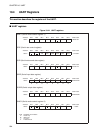
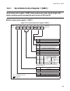
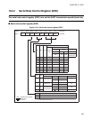
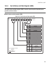
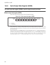
10.4.1 Serial Mode Control Register 1 (SMC1)
Serial mode control register 1 (SMC1) sets synchronous mode, stop bit length, data
length, parity/non-parity and select the port function of SCK and SO.
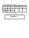
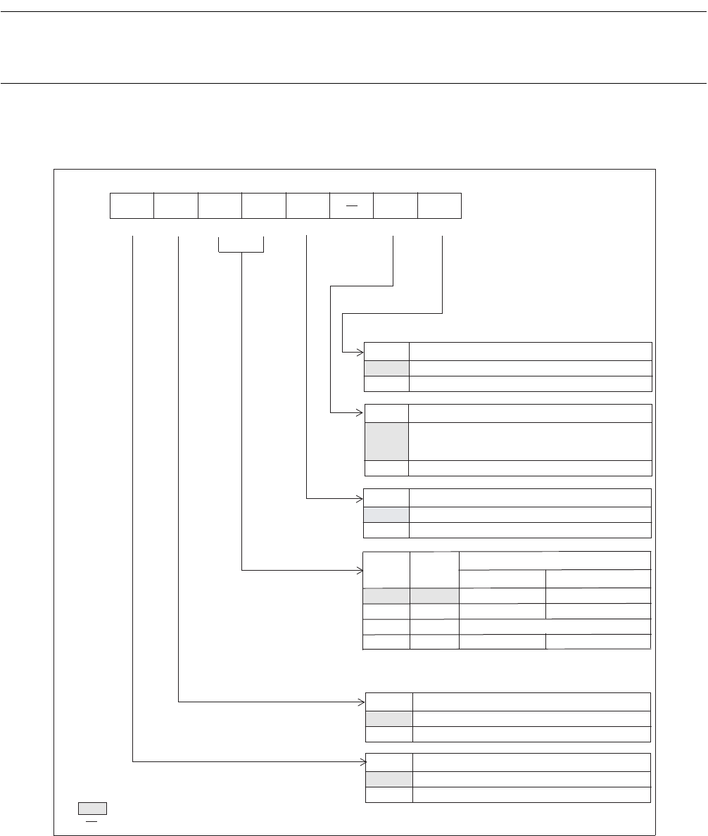
■ Serial mode control register 1 (SMC1)
Figure 10.4-2 Serial mode control register 1 (SMC1)
Address Bit 7 Bit 6 Bit 5 Bit 4 Bit 3 Bit 2 Bit 1 Bit 0 Initial value
0020
H
PEN SBL MC1 MC0 SMDE SCKE SOE 00000-00
B
R/W R/W R/W R/W R/W R/W R/W
SOE
Serial output enable bit
Serial clock enable bit
Operation mode control bit
Stop bit length control bit
Parity control bit
Transfer mode control bits
0 Functions as general-purpose I/O port (P44)
Functions as general-purpose I/O port (P45).
1
Functions as serial output (SO)
SCKE
0 When the port is set to input (DDR4:bit5 =0),
it also functions as serial clock input pin.
1 Functions as serial clock (SCK)
SMDE
0 Synchronous transfer
1 Asynchronous transfer
MC1 MC0
Mode Data length
0 0 0 5(4)
01 1 8(7)
10 Reserved
11 3
9(8)
Value in parantheses is initial value and indicates the
data length with parity.
SBL
0 2-bit length
1 1-bit length
PEN
0 Non-parity
1 Parity (odd/even selected by TD8/TP bit)
R/W : Readable and writable
: Initial value
: Unused