


217
CHAPTER 10 UART
10.7 Operation of Mode 0, 1, 3
The operation mode 0, 1 and 3 provide a serial communication function.
■ Operation of operation mode 0, 1, 3
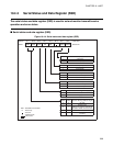
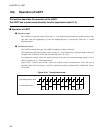
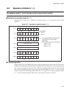
Settings shown in Figure 10.7-1 "Operation of operation mode 0, 1, 3" are necessary for the UART
operation.
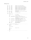
Figure 10.7-1 Operation of operation mode 0, 1, 3
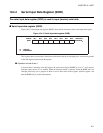
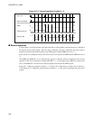
■ Transmit operation
Writing transmit data to the SODR register after reading from SSD register transfers the data written in the
SODR to the transmit shift register and initiates a parallel-serial conversion process. The converted transmit
data is sent to the serial data output pin with its LSB (Least Significant Bit) followed by other bits (LSB
first). When the SODR register gets ready for the next data, the TDRE bit is set to "1" and an interrupt
request is issued to CPU (if interrupt enabled, SSD: TIE = "1"). Figure 10.7-2 "Transmit operation in mode
0, 1, 3 " shows the transmit operation when mode 1, non-parity and 1 stop bit are selected.
Bit 7 Bit 6 Bit 5 Bit 4 Bit 3 Bit 2 Bit 1 Bit 0
SMC1
PEN SBL MC1 MC0 SMDE
SCKE SOE
** 1
SRC
CR CS1 CS0 RC2 RC1 RC0
SSD
RDRFORFETDRE TIE RIE
TD8
/TP
RD8
/RP
SIDR
Receive data stored
SODR
Transmit data written
SMC2
PSEN RSEL PDS1 PDS0
0
DDR4
: If non-parity selected in mode 3, these
are interpreted as TD8 and RD8,
respectively.
* : MC1 and MC0 should be set as follows:
mode 0 = "00
B"
mode 1 = "01
B"
mode 3 = "11
B"
: Used bit
1 : Set "1"
0 : Set "0"