


182
CHAPTER 9 8-BIT SERIAL I/O
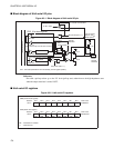
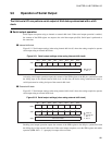
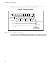
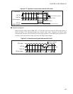
When the device being communicated with has completed the serial input operation (on the rising edge),
hold the external shift clock at the "H" level while waiting for next output data (idle state).
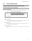
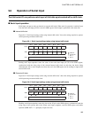
Figure 9.5-3 "8-bit serial output operation" shows the 8-bit serial output operation.
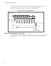
Figure 9.5-3 8-bit serial output operation
■ Operation at completion of serial output
The 8-bit serial I/O sets the interrupt request flag bit (SMR: SIOF = "1") and clears the serial I/O transfer
start bit (SMR: SST = "0") on the rising edge of the shift clock after the serial data of the eighth bit is
output.
01234567
Bit 7
#7
Bit 6
#6
Bit 5
#5
SDR
Bit 4
#4
Bit 3
#3
Bit 2
#2
Bit 1
#1
Bit 0
#0
#0 #1 #2 #3 #4 #5 #6 #7
For LSB first
SO pin
Serial output
data
Shift clock
SIOF bit
Cleared by the program.
SST bit
Transfer start
Automatically cleared
when transfer completes.
Interrupt request