164
CHAPTER 8 PULSE WIDTH COUNT TIMER (PWC)
8.9 Notes on Using Pulse Width Count Timer
This section lists points to note when using the pulse width count timer.
■ Notes on using pulse width count timer
●
Error
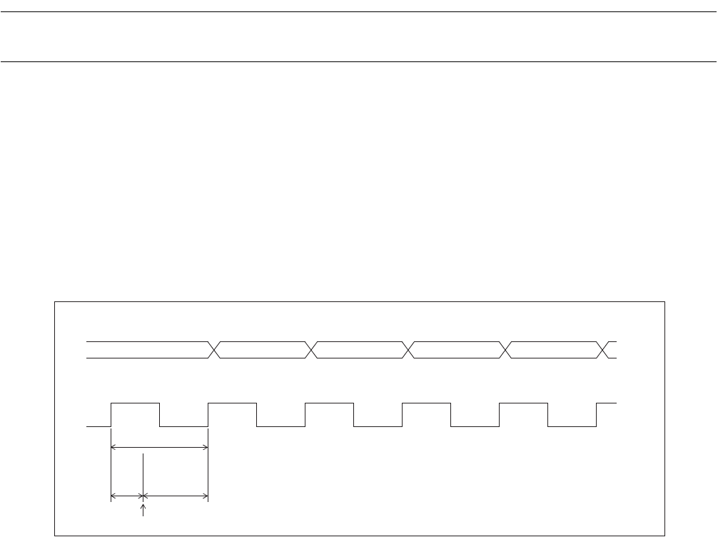
When using the interval timer function, activating the counter by program is not synchronized with the start
of counting-down using the selected internal count clock. Therefore, the time from activating the counter
until an underflow occurs may be shorter than the theoretical time by a maximum of one cycle of the count
clock.
Figure 8.9-1 "Error on starting counter operation" shows the error that occurs on starting counter operation.
Figure 8.9-1 Error on starting counter operation
●
Notes on setting by program
• Do not modify the contents of the PWC pulse width control register 2 (PCR2) when the interval timer
function or pulse width measurement function is operating (PCR1: EN = "1").
• Stop the counter (EN = "0"), disable interrupts (IE = "0"), and clear the interrupt request flag bits (UF,
IR, BF = "000
B
") in the PCR1 register before switching between the interval timer function and pulse
width measurement function (PCR2: FC).
• Interrupt processing cannot return if the interrupt request flag bit (PCR1: UF, IR, or BF) is "1" and the
interrupt request enable bit is enabled (PCR1: IE = "1"). Always clear the interrupt request flag bit.
• If a previous measurement value has not been read when performing continuous pulse width
measurement for pulse width measurement function, new measurement values are not transferred to the
PWC reload buffer register (RLBR). The RLBR maintains the previous value. Always read the
measurement value before the next underflow (01
H
--> 00
H
) when measuring long pulse widths.
• The interrupt request flag bit (PCR1: UF, IR, or BF) is not set if the counter is disabled (PCR1: EN =
"0") at the same time as an interrupt source is generated.
Counter value
Set value: n
n-1 n-2 n-3 n-4
Count clock
One cycle
Error
Cycle of
set value n
Counter activate


