


251
CHAPTER 12 LCD CONTROLLER/DRIVER
12.4.1 Output Waveforms during LCD Controller/Driver
Operation (1/2 Duty Ratio)
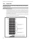
The display drive output is a multiplex drive-type two-frame a.c. waveform. In the 1/2
duty ratio mode, the only common outputs are COM0 and COM1. (COM2 and COM3 are
not used.)
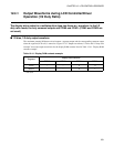
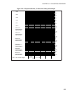
■ 1/2 bias, 1/2 duty output waveform
The maximum potential difference exists between a segment output and the corresponding common output
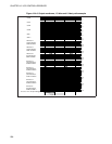
when the segment (LCD cell) is turned on. Figure 12.4-2 "Output waveforms, 1/2 bias and 1/2 duty ratio
example" shows the output waveforms for the display RAM contents listed in Table 12.4-1 "Display RAM
contents example".
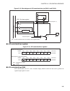
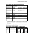
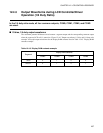
Table 12.4-1 Display RAM contents example
Segment
Display RAM contents
COM3 COM2 COM1 COM0
SEGn −−00
SEGn+1 −−01
−: Not used