


200
CHAPTER 10 UART
●
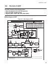
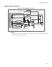
Baud rate generator and serial clock generator
This block generates transmit/receive clocks from the outputs of baud rate generator, 8-bit PWM timer or
external clock.
●
Date receive control circuit
The receive control circuit consists of the receive byte counter, the start bit detection circuit and the receive
parity circuit.
The receive byte counter counts number of data bit received and generates an interrupt after having
received data of the specified length.
The start bit detection circuit detects start bit from the serial input pin and starts to shift the following data
bit received into the shifter.
The receive parity circuit stores a parity bit after receiving data with a parity. When 9-bit long data is
received, the receive parity circuit stores the last bit received.
●
Data transmit control circuit
The transmit control circuit consists of a transmission byte counter and a transmission parity circuit.
The transmit byte counter counts number of data bytes transmit and generates an interrupt after having
received a data of the set length.
The transmission circuit generates a parity bit when transmitting data with a parity bit. When 9-bit long
data is sent, the MSB of the transmit data is sent.
●
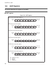
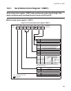
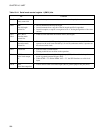
Serial mode control register 1 (SMC1)
This register controls operating modes in the UART. The register is used to select parity/non-parity, stop
bit length, operating mode (data length), synchronous/asynchronous, enable/disable of UART serial clock
output (SCK) and enable/disable of serial data output (SO).
●
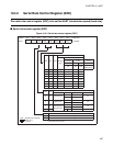
Serial mode control register 2 (SMC2)
This register controls UART starting/stopping operation, UART/SIO function and input clock divider of
the baud rate generator.
●
Serial rate control register (SRC)
This register controls the data transmission rate (baud rate). The register selects transfer rate generated by
the baud rate generator.
●
Serial status and data register (SSD)
This register is used to select or show transmit/receive operation, to indicate error status, and to select
received/transmitted data parity.
●
Serial input data register (SIDR)
This register holds received data. Serial data received is converted to parallel data and stored in the register.
When the data length is set to 7 bits, bit 7 does not have meaning.