


58
CHAPTER 3 CPU
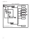
3.7.1 Operating States in Standby Mode
This section describes the operating states of the CPU and peripheral functions in
standby mode.
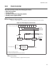
■ Operating states during standby mode
●
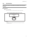
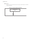
Pin States in Standby Mode
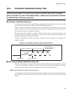
Almost all I/O pins will either keep the state they were placed in, or go to the high-impedance state
according to the pin state control bit of the standby control register (STBC: SPL) just prior to going to the
stop mode. This is true regardless of the clock mode.
See Appendix E "MB89950/950A Series Pin States" for pin states in standby mode.
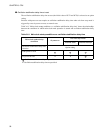
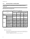
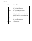
Table 3.7-1 Operating states of the CPU and peripheral functions in standby mode
Function
Main clock mode
Run Sleep
Stop
(SPL = "0")
Stop
(SPL = "1")
Main clock Operating Operating Stop Stop
CPU
Instructions Operating Stop Stop Stop
ROM
Operating Hold Hold Hold
RAM
Peripheral
functions
I/O ports Operating Hold Hold
Hi-Z
(*1)
Timebase timer Operating Operating Stop Stop
8-bit PWM timer Operating Operating Stop Stop
8-bit PWC timer Operating Operating Stop Stop
Watchdog timer Operating Stop Stop Stop
LCD controller/driver Operating Operating Stop Stop
External Interrupts Operating Operating Operating Operating
Serial I/O Operating Operating Stop Stop
UART Operating Operating Stop Stop
*1: If pull-up is selected, it will be "H" level.