


155
CHAPTER 8 PULSE WIDTH COUNT TIMER (PWC)
8.4 Pulse Width Count Timer Interrupts
The pulse width count timer has the following two interrupts:
• Counter value underflow (01
H
--> 00
H
) for the interval timer function
• Measurement completion and buffer full for the pulse width measurement function
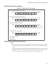
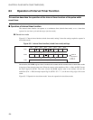
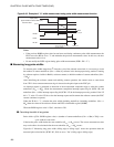
■ Interrupt for the interval timer function
The counter counts down from the set value on the selected internal count clock. When an underflow
occurs, the underflow (01
H
--> 00
H
) interrupt request flag bit (PCR1: UF) is set to "1". At this time, an
interrupt request (IRQ3) to the CPU is generated if the interrupt request enable bit is enabled (PCR1: IE =
"1"). Write "0" to the UF bit in the interrupt processing routine to clear the interrupt request.
References:
• The UF bit is not set if the counter is stopped (PCR1: EN = "0") at the same time as the counter value
underflows (01
H
--> 00
H
).
• An interrupt request is generated immediately if the UF bit is "1" when the IE bit is changed from
disabled to enabled ("0" --> "1").
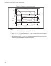
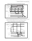
■ Interrupt for pulse width measurement function
When the specified measurement completion edge is detected, the measurement completion interrupt
request flag bit (PCR1: IR) and the buffer full flag bit (PCR1: BF) are set to "1". Also, when a counter
underflow (01
H
--> 00
H
) occurs due to measurement of a long pulse, the UF bit is set to "1". At this time,
an interrupt request (IRQ3) to the CPU is generated if the interrupt request enable bit is enabled (PCR1: IE
= "1"). Write "0" to the IR and UF bit in the interrupt processing routine to clear the interrupt request. Also
read the PWC reload buffer register (RLBR) to clear the BF bit to "0".
References:
• The IR and BF bit are not set if the counter is stopped (PCR1: EN = "0") at the same time as the
specified measurement completion edge is detected.
• An interrupt request is generated immediately if the IR, BF, or UF bit is "1" when the IE bit is changed
from disabled to enabled ("0" --> "1").
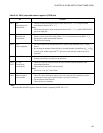
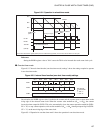
■ Register and vector table for pulse width count timer interrupt
See Section 3.4-2 "Interrupt Processing" for details on the operation of interrupt.
Table 8.4-1 Register and vector table for pulse width count timer interrupt
Interrupt
Interrupt level setting register Vector table address
Register Setting bits Upper Lower
IRQ3
ILR1 (007C
H
)
L31 (Bit 7) L30 (Bit 6)
FFF4
H
FFF5
H