


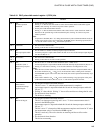
145
CHAPTER 8 PULSE WIDTH COUNT TIMER (PWC)
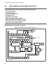
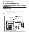
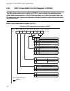
●
Count clock selector
Selects a count clock for the 8-bit down counter from the three available internal count clocks.
●
8-bit down counter
The 8-bit down counter starts to count from the value set in the PWC reload buffer register (RLBR) when
operating as an interval timer, and from FF
H
when performing pulse width measurement. When an
underflow (01
H
--> 00
H
) occurs, the counter inverts the timer output bit (PCR2: TO).
●
Input pulse edge detector
Operates when the pulse width measurement function is selected, and starts or stops the 8-bit down counter
when an edge input from the PWC pin matches the edge specified by the PWC pulse width control register
2 (PCR2).
●
Noise filter circuit
The PWC input is sampled by the clock pulse selected by the sample clock selector. The sample input
signal is integrated to clear the noise.
●
Noise filter clock selector
Selects a sampling clock for the noise filter circuit from three count clocks of timebase timer.
●
RLBR register
When operating in reload timer mode of the interval timer function, the RLBR register value is re-loaded to
the counter and the count continues whenever a counter value underflow (01
H
--> 00
H
) occurs.
When performing pulse width measurement, the value of the 8-bit down counter is transferred to the RLBR
register when measurement completes.
●
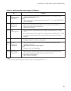
PCR1 and PCR2 register
These registers are used to select the function, set operating conditions, enable or disable operation, control
interrupts, and to check the PWC status.
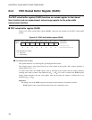
●
NCCR register
This register is used to select sampling clock pulse for the noise filter circuit.