225
CHAPTER 11 EXTERNAL INTERRUPT CIRCUIT (EDGE)
11.2 Block Diagram of the External Interrupt Circuit
The external interrupt circuit consists of the following two elements:
• Edge detect circuit 0, 1
• External interrupt control register (EIC)
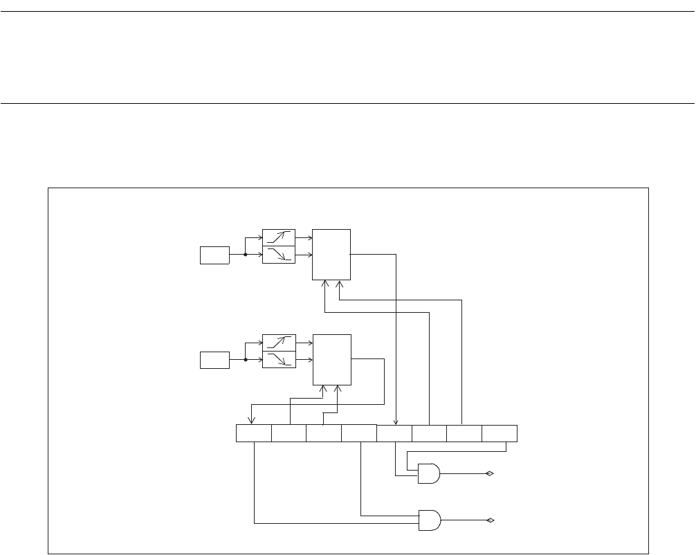
■ Block diagram of the external interrupt circuit
Figure 11.2-1 Block diagram of the external interrupt circuit
●
Edge detect circuit
If the polarity of an edge on the input signal to one of the external interrupt pins (INT0 - INT1) matches the
edge polarity specified for the pin in the EIC register (SL01, SL00, SL11, SL10), the edge detect circuit
sets the corresponding external interrupt request flag bit (EIR0 - EIR1) to "1".
●
EIC register
The EIC register is used for operations such as edge selection, enabling or disabling interrupt requests, and
checking interrupt requests.
1
Selector
P42/PWC/INT1
IRQ1
Edge detect circuit 1
Pin
EIR1 SL11 SL10 EIE1
0
Selector
EIC
P46/INT0
IRQ0
Edge detect circuit 0
Pin
EIR0 SL01 SL00 EIE0
0
1


