


172
CHAPTER 9 8-BIT SERIAL I/O
●
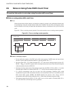
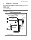
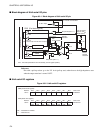
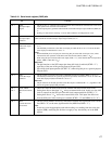
Shift clock control circuit
Selects the shift clock from one external and three internal clocks.
If an internal shift clock is selected, the shift clock can be output to the SCK pin. If external shift clock is
selected, the clock input from the SCK pin is used as the shift clock. The SDR register shifts in
synchronous with the shift clock and the shifted-out value is output to the SO pin. Similarly, the serial input
is obtained by shifting the SI pin input to the SDR register.
●
Shift clock counter
The shift clock counter counts the number of SDR register shifts generated by the shift clock and overflows
after eight shifts.
The overflow clears the serial I/O transfer start bit in the SMR register (SST = "0") and sets the interrupt
request flag (SIOF = "1"). The shift clock counter stops counting when serial transfer halts (SST = "0").
The shift clock counter is cleared when serial transfer restarts (SST = "1").
●
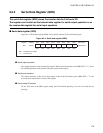
SDR register
The SDR register is used to store the transfer data. Data written to this register is converted to serial and
output. Serial input is converted to parallel data and stored in this register.
●
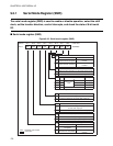
SMR register
The SMR register is used to enable or disable serial I/O operation, select the shift clock, set the transfer
(shift) direction, control interrupts, and check the serial I/O status.