


94
CHAPTER 4 I/O PORTS
4.6.1 Port 4 Registers (PDR4, DDR4)
This section describes the port 4 registers.
■ Port 4 register functions
●
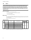
Port 4 data register (PDR4)
The PDR4 register holds the pin states. Therefore, when used as an output port that is not a peripheral
output, it reads out as the same state ("0" or "1") as that of the output data latch; and when it is an input
port, the output latch state cannot be read out.
Reference:
As the bit manipulation instructions (SETB and CLRB) read the output latch data rather than the pin
level, the instructions do not change the output latch values for bits other than the bit being set or
cleared.
●
Port 4 data direction register (DDR4)
The DDR4 register sets the direction (input or output) for each pin (bit).
Setting "1" to the bit corresponding to a port (pin) sets the pin as an output port. Setting "0" sets the pin as
an input port.
●
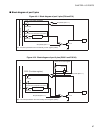
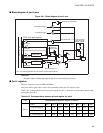
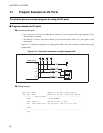
Settings as a peripheral output
To use a peripheral that has an output pin, set the peripheral output enable bit for that pin to the "enable"
state. As can be seen in the block diagram, the peripheral has precedence over the general-purpose port for
use of the output pin. Once the peripheral output is enabled, the states set in the PDR4 and DDR4 registers
are no longer valid, and do not affect the data output by the peripheral, or the enabling of the output.
●
Settings as a peripheral input
To use a peripheral that has a port 4 pin as an input pin, set that pin as an input port. The output latch data
for that pin will no longer be valid.
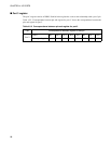
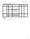
Table 4.6-3 "Port 4 PDR and DDR register function" lists the functions of the port 4 PDR and DDR
registers.