


113
CHAPTER 6 WATCHDOG TIMER
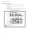
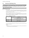
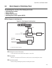
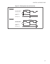
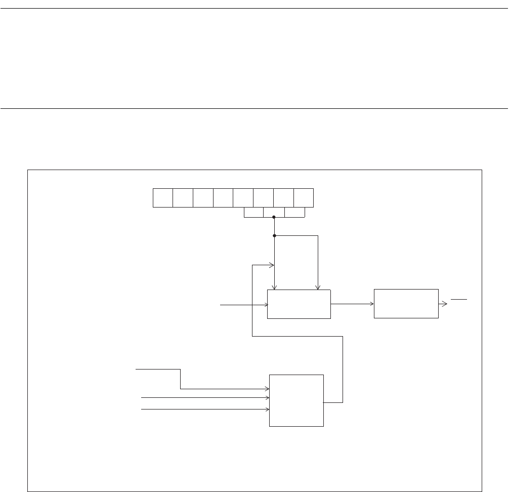
6.2 Block Diagram of Watchdog Timer
The watchdog timer consists of the following four blocks:
• Watchdog timer counter
• Reset controller
• Counter clear controller
• Watchdog timer control register (WDTC)
■ Block diagram of watchdog timer
Figure 6.2-1 Block diagram of watchdog timer
●
Watchdog timer counter (2-bit counter)
A 2-bit counter that uses the timebase timer output as a count clock.
●
Reset controller
Generates a reset signal to the CPU when an overflow occurs on the watchdog timer counter.
●
Counter clear controller
Controls clearing and halting the operation of watchdog timer counter.
————WTE3 WTE2 WTE1 WTE0
WDTC register
Counter clear
2-bit counter
RST
Reset controller
controller
2
21
/F
CH
(Timebase timer output)
Overflow
Watchdog timer
Start
Clear
Sleep mode start
Stop mode start
Clear signal
from timebase
timer
FCH: Main clock oscillation frequency