


249
CHAPTER 12 LCD CONTROLLER/DRIVER
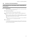
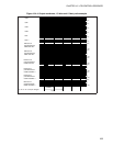
Table 12.3-4 "Common outputs and display RAM bits used in each duty ratio mode" shows the relationship
between duty ratio mode, common outputs, and display RAM.
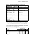
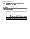
Table 12.3-3 Segment outputs, display RAM locations, and sharing port pins
Segment/common output
pins used (mask option)
Corresponding
display RAM area
General-purpose ports sharing same pins
SEG0 to SEG19 (20 pins)
64
H
to 6D
H
P00 to P07, P10 to P17, P20 to P25 (22 pins)
SEG0 to SEG19, SEG40 to
SEG41 (22 pins)
64
H
to 6D
H
78
H
P00 to P07, P10 to P17, P20 to P23 (20 pins)
SEG0 to SEG19, SEG36 to
SEG41 (26 pins)
64
H
to 6D
H
76
H
to 78
H
P00 to P07, P10 to P17 (16 pins)
SEG0 to SEG27, SEG36 to
SEG41 (34 pins)
64
H
to 71
H
76
H
to 78
H
P10 to P17 (8 pins)
SEG0 to SEG31, SEG36 to
SEG41 (38 pins)
64
H
to 73
H
76
H
to 78
H
P14 to P17 (4 pins)
SEG0 to SEG39 (40 pins)
64
H
to 77
H
P24 to P25 (2 pins)
SEG0 to SEG33, SEG36 to
SEG41 (40 pins)
64
H
to 74
H
76
H
to 78
H
P16 to P17 (2 pins)
SEG0 to SEG34, SEG36 to
SEG41 (41 pins)
64
H
to 78
H
P17 (1 pin)
SEG0 to SEG41 (42 pins)
64
H
to 78
H
None
Note:
Locations in the display RAM area that are not required for display data can be used as regular RAM.
If any customer wants to choose the mask option combination which is not shown in Table 12.3-3
"Segment outputs, display RAM locations, and sharing port pins", please inform Fujitsu for special
testing arrangement.
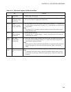
Table 12.3-4 Common outputs and display RAM bits used in each duty ratio mode
Duty ratio
setting
Common outputs used
Display data bit used
bit7 bit6 bit5 bit4 bit3 bit2 bit1 bit0
1/2 COM0 to COM1 (2 pins) −− −−
1/3 COM0 to COM2 (3 pins) −−
1/4 COM0 to COM3 (4 pins)
: Used
−: Not used