


140
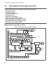
CHAPTER 7 8-BIT PWM TIMER
■ Program example for PWM timer function
●
Processing description
• Generates a PWM wave with a duty ratio of 50%. Then, changes the duty ratio to 25%.
• Does not generate interrupts.
• For a 5 MHz main clock oscillation frequency (F
CH
), selecting the interval 16 t
inst
count clock gives a
PWM wave cycle of 16 x 4/5 MHz x 256 = 3.277 ms.
• The following shows the COMR register value required for a duty ratio of 50%:
COMR register value = 50/100 x 256 = 128 (080
H
)
●
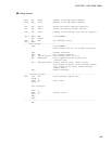
Coding example
CNTR EQU 0012H ; Address of the PWM control register
COMR EQU 0013H ; Address of the PWM compare register
TPE EQU CNTR:3 ; Define the counter operation enable bit.
;-----Main program---------------------------------------------------------------
CSEG ; [CODE SEGMENT]
:
CLRB TPE ; Stop counter operation.
MOV COMR,#80H ; Set "H" width of pulse. Duty ratio = 50%
MOV CNTR,#10011010B ; Operate PWM timer, select 16 tinst,
start counter operation, clear interrupt request
flag, enable PWM pin output, and disable
interrupt request output.
:
:
MOV COMR,#40H ; Change the duty ratio to 25% (effective from
the next PWM wave cycle).
:
ENDS
;--------------------------------------------------------------------------------
END