


148
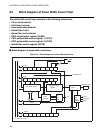
CHAPTER 8 PULSE WIDTH COUNT TIMER (PWC)
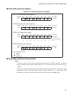
8.3.1 PWC Pulse Width Control Register 1 (PCR1)
The PWC pulse width control register 1 (PCR1) is used to enable or disable functions,
control interrupts and check the state of the pulse width count timer.
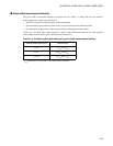
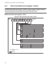
■ PWC pulse width control register 1 (PCR1)
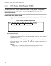
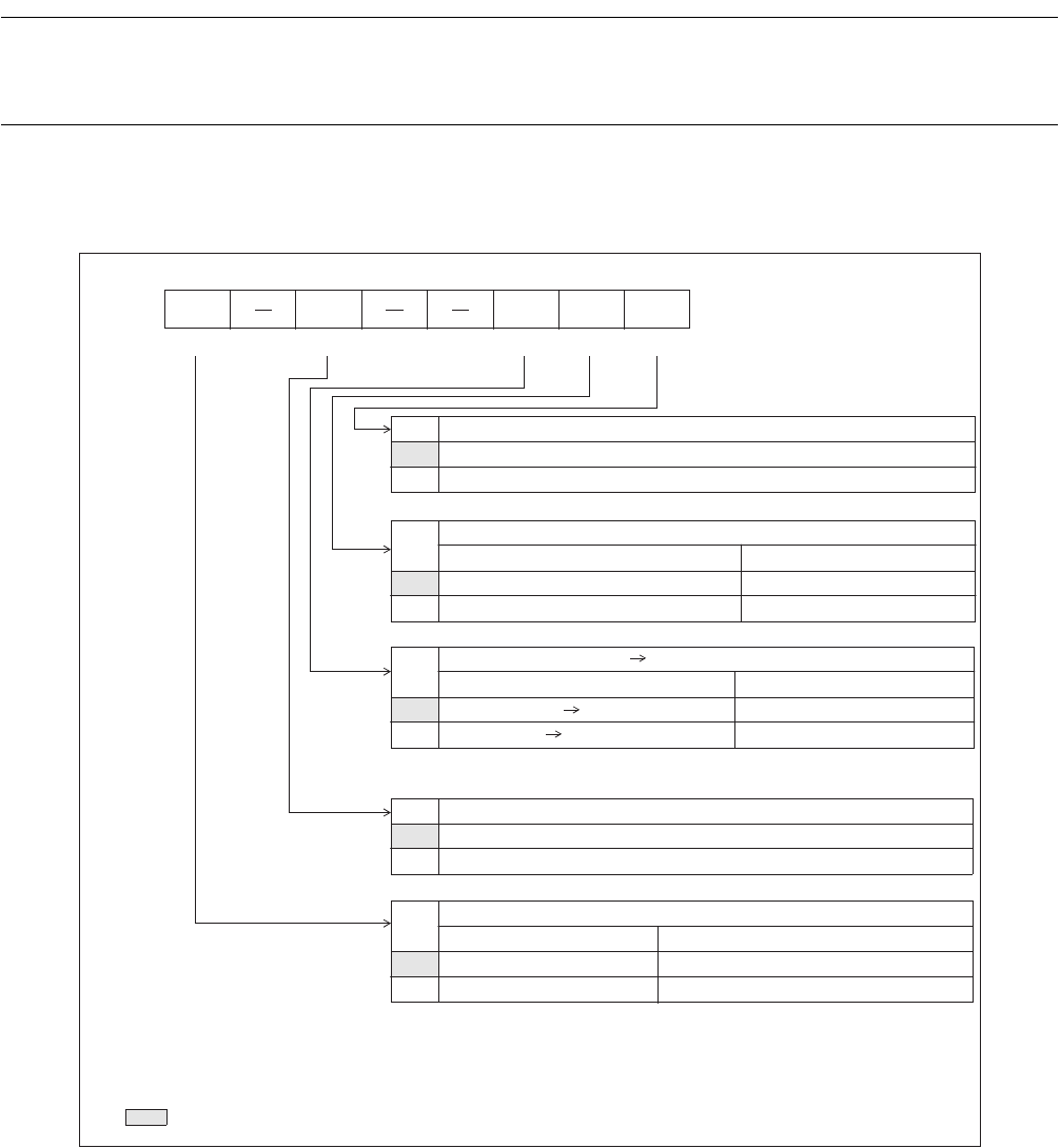
Figure 8.3-3 PWC pulse width control register 1 (PCR1)
Address Bit 7 Bit 6 Bit 5 Bit 4 Bit 3 Bit 2 Bit 1 Bit 0 Initial value
0014
H
EN IE UF IR BF 0-0--000
B
R/W R/W R/W R/W R
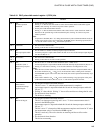
BF Buffer full
flag bit
0 No pulse width measurement value.
1 Pulse width measurement value.
IR
Measurement completion
i
nterrupt request flag bit
Read Write
0
Pulse width measurement has not completed. Clears this bit.
1
Pulse width measuremen
No effect. The bit does not change.
UF
Underflow (01
H
00
H
) in
terrupt request flag bit
Read Write
0
No underflow (01
H
00
H
) on counter. Clears this bit.
1
Underflow (01
H
00
H
) on counter. No effect. The bit does not change.
The UF, IR, and BF bits are interrupt request flag bits.
IE Interrupt request enable bit
0 Disables interrupt request output.
1 Enables interrupt request output.
EN
Counter operation enable b it
Timer function Pulse width measure function
0 Count disables/stops. Pulse width measure disables/stops.
1 Count enables/starts. Pulse width measure enables/starts.
R/W : Readable and writable
R : Read-only
— : Unused
: Initial value
t has completed.