


157
CHAPTER 8 PULSE WIDTH COUNT TIMER (PWC)
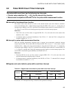
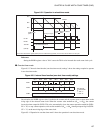
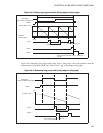
Figure 8.5-2 Operation in reload timer mode
Reference:
Setting the RLBR register value to "01
H
" causes the TO bit to be inverted after each count clock cycle.
●
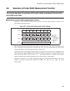
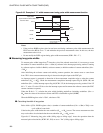
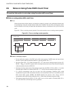
One-shot timer mode
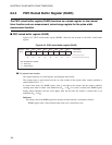
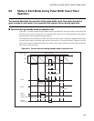
Figure 8.5-3 "Interval timer function (one-shot timer mode) settings" shows the settings required to operate
in one-shot timer mode.
Figure 8.5-3 Interval timer function (one-shot timer mode) settings
On activation, the RLBR register value is loaded to the counter and the counter starts to count down on the
rising edge of the selected count clock. When the counter value underflows (01
H
--> 00
H
), the counter
inverts the timer output bit (PCR2: TO) value, automatically clears the counter operation enable bit (PCR1:
EN = "0") to stop counter operation, and sets the underflow (01
H
--> 00
H
) interrupt request flag bit (PCR1:
UF = "1") on the next rising edge of the count clock.
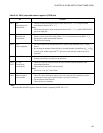
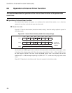
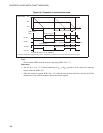
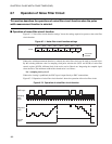
Figure 8.5-4 "Operation in one-shot timer mode" shows the operation in one-shot timer mode.
Counter value
FF
H
80
H
00H
Timer cycle
Cleared by the program
Time
UF bit
EN bit
TOE bit
RLBR value
(FF
H)
RLBR value is modified*
(FF
H 80H)
Reload
(TO bit)
For an initial value of “0”
*: If the PWC reload buffer register (RLBR) value is modified during operation, the new value will be effective in next cycle.
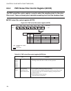
PCR1 EN IE UF IR BF
1
Bit 7 Bit 6 Bit 5 Bit 4 Bit 3 Bit 2 Bit 1 Bit 0
XX
XX
X
PCR2 FC RM TO
C1 C0 W1 W0
01
RLBR Sets interval time (counter initial value).
: Used bit
: Unused bit
1: Set "1".
0: Set "0".