


25
CHAPTER 3 CPU
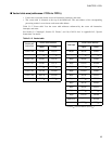
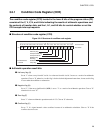
■ Vector table area (addresses: FFC0
H
to FFFF
H
)
• Used as the vector table for the vector call instruction, interrupts, and resets.
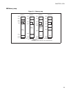
• The vector table is allocated at the top of the ROM area. The start address of the corresponding
processing routine is set as data at each vector table address.
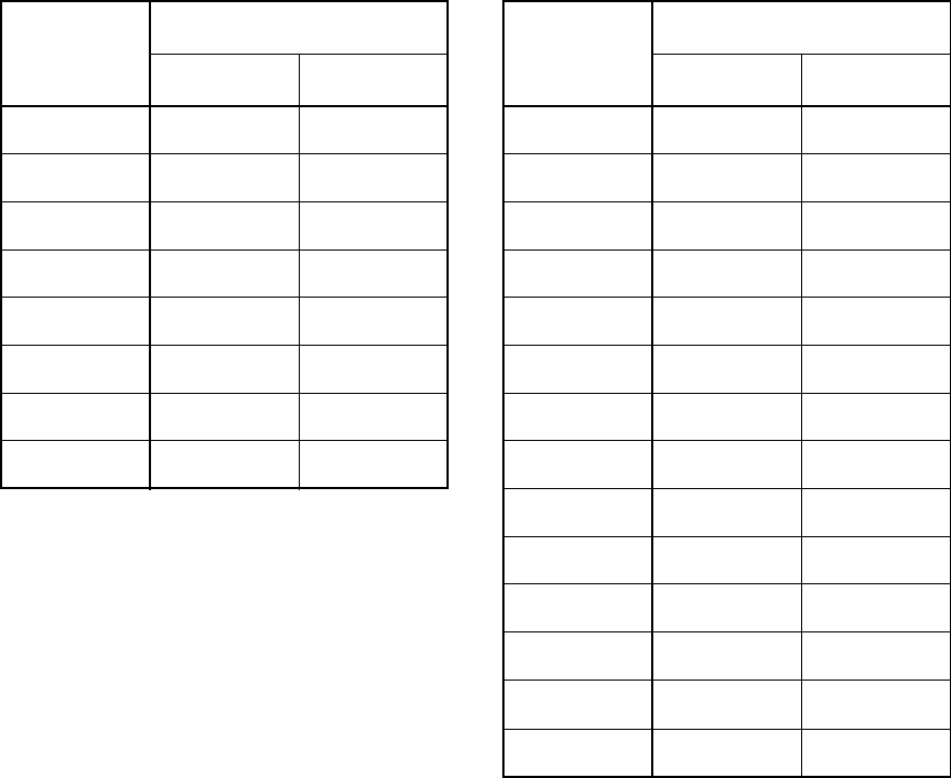
Table 3.1-2 "Vector table" lists the vector table addresses referenced by the vector call instruction,
interrupts, and resets.
See Section 3.4 "Interrupts", Section 3.5 "Resets", and "(6) CALLV #vct" in Appendix B.2, "Special
Instructions" for details.
Table 3.1-2 Vector table
Vector call
instruction
Vector table address
Interrupts
Vector table address
Upper Lower Upper Lower
CALLV #0 FFC0
H
FFC1
H
IRQB FFE4
H
FFE5
H
CALLV #1 FFC2
H
FFC3
H
IRQA FFE6
H
FFE7
H
CALLV #2 FFC4
H
FFC5
H
IRQ9 FFE8
H
FFE9
H
CALLV #3 FFC6
H
FFC7
H
IRQ8 FFEA
H
FFEB
H
CALLV #4 FFC8
H
FFC9
H
IRQ7 FFEC
H
FFED
H
CALLV #5 FFCA
H
FFCB
H
IRQ6 FFEE
H
FFEF
H
CALLV #6 FFCC
H
FFCD
H
IRQ5 FFF0
H
FFF1
H
CALLV #7 FFCE
H
FFCF
H
IRQ4 FFF2
H
FFF3H
IRQ3 FFF4
H
FFF5
H
IRQ2 FFF6
H
FFF7
H
IRQ1 FFF8
H
FFF9
H
IRQ0 FFFA
H
FFFB
H
Mode data
--
(*1)
FFFD
H
Reset vector FFFE
H
FFFF
H
*1: FFFC
H
is not available. (Set FF
H
.)