


123
CHAPTER 7 8-BIT PWM TIMER
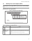
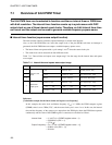
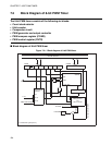
■ PWM timer function
The PWM timer function has 8-bit resolution and can control the "H" and "L" width of one cycle.
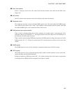
• As the resolution is 1/256, pulses can be output with duty ratio of between 0 and 99.6%.
• The cycle of the PWM wave can be selected from four types.
• The PWM timer can be used as a D/A converter by connecting the output to a low-pass filter.
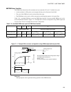
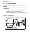
Table 7.1-2 "Available PWM wave cycle for PWM timer function" lists the available PWM wave cycles
for the PWM timer function. Figure 7.1-1 "Example D/A converter configuration using PWM output and
low-pass filter" shows an example D/A converter configuration.
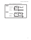
Figure 7.1-1 Example D/A converter configuration using PWM output and low-pass filter
Reference:
Interrupt requests are not generated during operation of the PWM function.
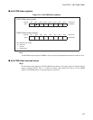
Table 7.1-2 Available PWM wave cycle for PWM timer function
123 4
Internal count clock 8-bit timer output cycle times
Count clock cycle
1 t
inst
2
4
t
inst
2
6
t
inst
2 t
inst
to 2
9
t
inst
2
3
t
inst
to 2
11
t
inst
2
6
t
inst
to 2
14
t
inst
PWM wave cycle
2
8
t
inst
2
12
t
inst
2
14
t
inst
2
9
t
inst
to 2
17
t
inst
2
11
t
inst
to 2
19
t
inst
2
14
t
inst
to 2
22
t
inst
t
inst
: Instruction cycle
Analog output waveform
PWM output waveform
PWM pin
PWM output
R
C
Analog output (Va)
Tr
Va
Vcc
TH TL
T
Va
t
Vcc
0
The relationship between the analog output voltage
and PWM output waveform is:
Va/Vcc = T
H
/T
Tr is the time taken for the output to stabilize.