


160
CHAPTER 8 PULSE WIDTH COUNT TIMER (PWC)
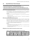
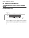
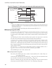
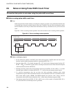
Figure 8.6-2 Example of "H" width measurement using pulse width measurement function
Notes:
• If the previous RLBR register value has not been read during continuous pulse width measurement, the
PWC leaves the BF bit set to "1" and maintains the previous measurement value. In this case, the new
measurement value is lost.
• Do not modify the PCR2 register during pulse width measurement (PCR1: EN = "1").
■ Measuring long pulse widths
To measure pulse widths longer than 2
8
times the cycle of the selected count clock, it is necessary to count
the number of counter underflows (01
H
--> 00
H
) by software in the interrupt processing routine. Counting
by software requires a buffer in RAM (a software counter) to hold the number of counter underflows (01
H
-
-> 00
H
).
After initializing the software counter and enabling counter operation, the counter starts to count down
from "FF
H
" when a measurement start edge is detected on the pulse input to the PWC pin.
An interrupt request is generated on detection of the measurement completion edge or when the counter
underflows (01
H
--> 00
H
). Check the measurement completion interrupt request flag bit (PCR1: IR) and
underflow (01
H
--> 00
H
) interrupt request flag bit (PCR1: UF) in the interrupt processing routine. If the UF
bit is "1", write "0" to the UF bit to clear the interrupt request and increment the software counter (the PWC
counter continues to operate).
When the IR bit is "1", calculate the pulse width (including underflows (including underflows (01
H
-->
00
H
) from the values of the software counter and PWC reload buffer register (RLBR).
When the RLBR register value is "00
H
", calculate as 256.
●
Calculating the width of long pulses
Pulse width = [(256 - RLBR register value) + (number of counter underflows (01
H
--> 00
H
) x 256)] x one-
cycle width of count clock
Calculate the pulse width before the next underflow (01
H
--> 00
H
) occurs. The correct measurement value
may not be able to be calculated after the next underflow (01
H
--> 00
H
) occurs.
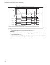
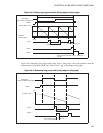
Figure 8.6-3 "Measuring long pulse width (falling edge to falling edge)" shows the operation when the
measured pulse selection bits (PCR2: W1, W0) are set to "11
B
" (falling edge to falling edge).
Input pulse
(Input waveform to the PWC pin)
Counter value
FF
H
EN bit
IR bit
BF bit
"H" width
Counter operation
Time
Cleared by the program
Data transferred from down
counter to RLBR
RLBR read