


98
CHAPTER 4 I/O PORTS
4.7 Program Example for I/O Ports
This section gives an example program for using the I/O ports.
■ Program example for I/O ports
●
Processing description
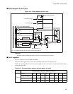
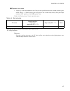
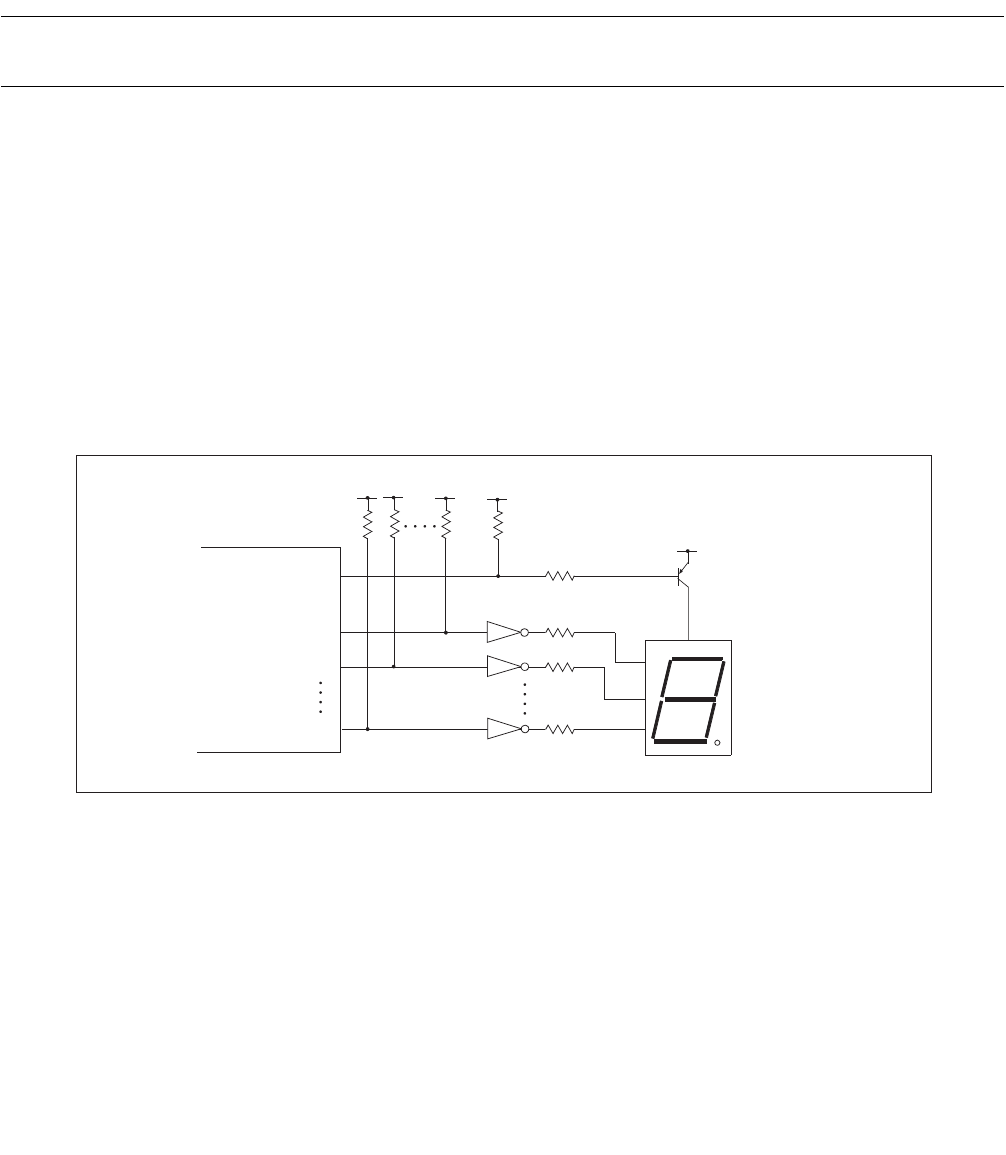
• Port 0 and port 1 are used to illuminate all elements of seven segment LED (eight segments if the
decimal point is included).
• The P00 pin is used for the anode common pin of the LED and the P10 to P17 pins operate as the
segment pins.
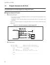
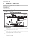
Figure 4.7-1 "Connection example for an eight segment LED" shows the connection example for an eight
segment LED.
Figure 4.7-1 Connection example for an eight segment LED
●
Coding example
P10
P16
P17
P00
MB89950/950A
PDR0 EQU 0000H ;Address of the port 0 data register
DDR0 EQU 0001H ;Address of the port 0 direction register
;---------------Main program--------------------------------------------
CSEG ; [CODE SEGMENT]
:
CLRB PDR0:0 ;Set P00 to the "L" level
MOV PDR1, #11111111B ;Set all port 1 pins to the "H" level
:
ENDS
;-----------------------------------------------------------------------
END