


147
CHAPTER 8 PULSE WIDTH COUNT TIMER (PWC)
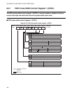
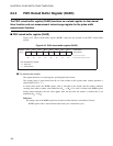
■ Pulse width count timer registers
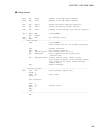
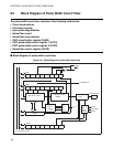
Figure 8.3-2 Pulse width count timer registers
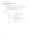
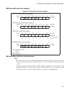
■ Pulse width count timer interrupt source
IRQ3:
For both the interval timer and pulse width measurement function, the PWC generates an interrupt
request if interrupt request output is enabled (PCR1: IE = "1") when the counter value underflows (01
H
--> 00
H
).
For the pulse width measurement function, the PWC generates an interrupt request for the pulse width
measurement function if interrupt request output is enabled (PCR1: IE = "1") when pulse width
measurement completes or a pulse width measurement value remains in the RLBR register.
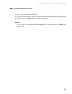
PCR1 (PWC pulse width control register 1)
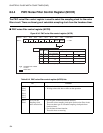
PCR2 (PWC pulse width control register 2)
RLBR (PWC reload buffer register)
NCCR (Noise filter control register)
Address Bit 7 Bit 6 Bit 5 Bit 4 Bit 3 Bit 2 Bit 1 Bit 0 Initial value
0014
H
EN IE UF IR BF 0-0--000
B
R/W R/W R/W R/W R
Address Bit 7 Bit 6 Bit 5 Bit 4 Bit 3 Bit 2 Bit 1 Bit 0 Initial value
0015
H
FC RM TO C1 C0 W1 W0 000-0000
B
R/W R/W R/W R/W R/W R/W R/W
Address Bit 7 Bit 6 Bit 5 Bit 4 Bit 3 Bit 2 Bit 1 Bit 0 Initial value
0016
H XXXXXXXXB
R/W R/W R/W R/W R/W R/W R/W R/W
……For the interval timer function
RRRRRRRR
……For the pulse width measurement
function
Address Bit 7 Bit 6 Bit 5 Bit 4 Bit 3 Bit 2 Bit 1 Bit 0 Initial value
0017
H
NCS1 NCS0 ------00
B
R/W R/W
R/W: Readable and writable
R :
Read-only
: Unused
X : Indeterminate