


30
CHAPTER 3 CPU
●
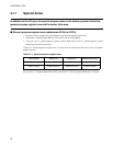
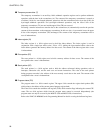
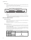
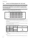
Carry flag (C)
Set to "1" when a carry from bit 7 or borrow to bit 7 occurs as a result of an arithmetic operation. Clear to
"0" otherwise. Set to the shift-out value in case of a shift instruction.
Figure 3.2-3 "Change of carry flag by shift instruction" shows the change of the carry flag by a shift
instruction.
Figure 3.2-3 Change of carry flag by shift instruction
Note:
The condition code register is part of the program status (PS) and cannot be accessed independently.
Reference:
In practice, the flag bits are rarely fetched and used directly. Instead, the bits are used indirectly by
instructions such as branch instructions (such as BNZ) or the decimal adjustment instructions (DAA,
DAS). The content of the flags after a reset is indeterminate.
■ Interrupt acceptance control bit
●
Interrupt enable flag (I)
Interrupt is enabled when this flag is set to "1" and the CPU accepts interrupt. Interrupt is prohibited when
this flag is set to "0" and the CPU does not accept interrupt.
The initial value after a reset is "0".
Normal practice is to set the flag to "1" by the SETI instruction and clear to "0" by the CLRI instruction.
●
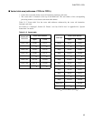
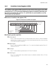
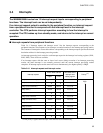
Interrupt level bits (IL1, IL0)
These bits indicate the level of the interrupt currently being accepted by the CPU. The value is compared
with the interrupt level setting registers (ILR1 to ILR3) which have a setting for each peripheral function
interrupt request (IRQ0 to IRQB).
Given that the interrupt enable flag is enabled (I = "1"), the CPU only performs interrupt processing for
interrupt requests with an interrupt level value that is less than the value of these bits. Table 3.2-1 "Interrupt
level" lists the interrupt level priorities. The initial value after a reset is "11
B
".
C
Bit 7 Bit 0
Bit 7 Bit 0
Left shift (ROLC) Right shift (RORC)
C
Table 3.2-1 Interrupt level
IL1 IL0 Interrupt level Priority
00
1
01
10 2
11 3
High
Low (no interrupt)