


229
CHAPTER 11 EXTERNAL INTERRUPT CIRCUIT (EDGE)
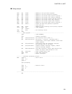
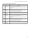
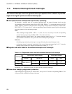
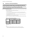
Table 11.3-2 External interrupt control register (EIC) bits
Bit Function
Bit 7 EIR1:
INT1 external
interrupt request flag
bit
• This bit is set to "1" when the edge selected by INT1 edge polarity selection bits
(SL11, SL10) is input to external interrupt pin INT1.
• An interrupt request is output when both this bit and INT1 interrupt request enable
bit (EIE1) are "1".
• Writing "0" clears the bit. Writing "1" has no effect and does not change the bit
value.
Bit 6
Bit 5
SL11, SL10:
INT1 edge polarity
mode selection bits
• Controls the mode of the input edge polarity of INT1 pin.
• Writing "00
B
" selects no edge detection, "01
B
" selects rising edge mode, "10
B
"
selects falling edge mode or "11
B
" selects both edge mode.
• Always write "0" into EIR1 when changing these bits.
Bit 4 EIE1:
INT1 interrupt
request enable bit
• Enables or disables output of interrupt requests to the CPU. An interrupt request is
generated when both this bit and INT1 external interrupt request flag bit (EIR1) are
"1".
Bit 3 EIR0:
INT0 external
interrupt request flag
bit
• This bit is set to "1" when the edge selected by INT0 edge polarity selection bits
(SL01, SL00) is input to external interrupt pin INT0.
• An interrupt request is output when both this bit and INT10 interrupt request enable
bit (EIE0) are "1".
• Writing "0" clears the bit. Writing "1" has no effect and does not change the bit
value.
Bit 2
Bit 1
SL01, SL00:
INT0 edge polarity
mode selection bits
• Controls the mode of the input edge polarity of INT0 pin.
• Writing "00
B
" selects no edge detection, "01
B
" selects rising edge mode, "10
B
"
selects falling edge mode or "11
B
" selects both edge mode.
• Always write "0" into EIR0 when changing these bits.
Bit 0 EIE0:
INT0 interrupt
request enable bit
• Enables or disables output of interrupt requests to the CPU. An interrupt request is
generated when both this bit and INT0 external interrupt request flag bit (EIR0) are
"1".