


154
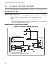
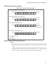
CHAPTER 8 PULSE WIDTH COUNT TIMER (PWC)
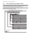
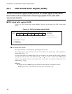
8.3.4 PWC Noise Filter Control Register (NCCR)
The PWC noise filter control register is used to select the sampling clock for the noise
filter circuit. There are three type of selectable sampling clock from the timebase timer.
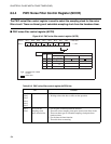
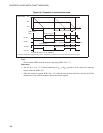
■ PWC noise filter control register (NCCR)
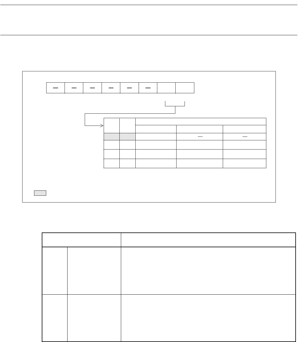
Figure 8.3-6 PWC noise filter control register (NCCR)
Address Bit 7 Bit 6 Bit 5 Bit 4 Bit 3 Bit 2 Bit 1 Bit 0 Initial value
0017
H
NCS1 NCS0 ------00
B
R/W R/W
NCS1 NCS0
Sampling clock pulse selection bits
Clock selected
F
CH
at 5 MHz
Noise pulse width
0 0
No noise filter
01
2
2
/F
CH
10
2
5
/F
CH
11
2
7
/F
CH
25.6 µs
6.4 µs
0.8 µs
R/W : Readable and writable
— : Unused
: Initial value
128 µs
32 µs
4.0 µs
FCH: Main clock oscillation frequency
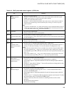
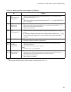
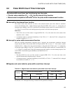
Table 8.3-3 PWC noise filter control register (NCCR) bits
Bit Function
Bit 7
Bit 6
Bit 5
Bit 4
Bit 3
Bit 2
Unused bits • The read value is indeterminate.
• Writing to these bits has no effect on the operation.
Bit 1
Bit 0
NCS1, NCS0:
Sampling clock
pulse selection bits
• For the pulse width measurement function:
These bits select sampling clock pulse for the noise filter circuit.
There are three type of selectable sampling clock pulse from
timebase timer.
• For the interval timer function:
These bits have no meaning.