231
CHAPTER 11 EXTERNAL INTERRUPT CIRCUIT (EDGE)
11.5 Operation of the External Interrupt Circuit
The external interrupt circuit can detect a specified edge on a signal input to an external
interrupt pin.
■ Operation of the external interrupt circuit
Figure 11.5-1 "External interrupt circuit settings" shows the settings required to operate the external
interrupt circuit.
Figure 11.5-1 External interrupt circuit settings
If the polarity of an edge on the input signal to one of the external interrupt pins (INT0 - INT1) matches the
edge polarity specified for the pin in the external interrupt control register (EIC: SL11, SL10, SL01, SL00),
the external interrupt circuit sets the external interrupt request flag bit (EIC: EIR0 - EIR1) to "1".
The external interrupt request flag bit is set when the edge polarity match occurs, regardless of the value of
the interrupt request enable bit (EIC: EIE0 - EIE1).
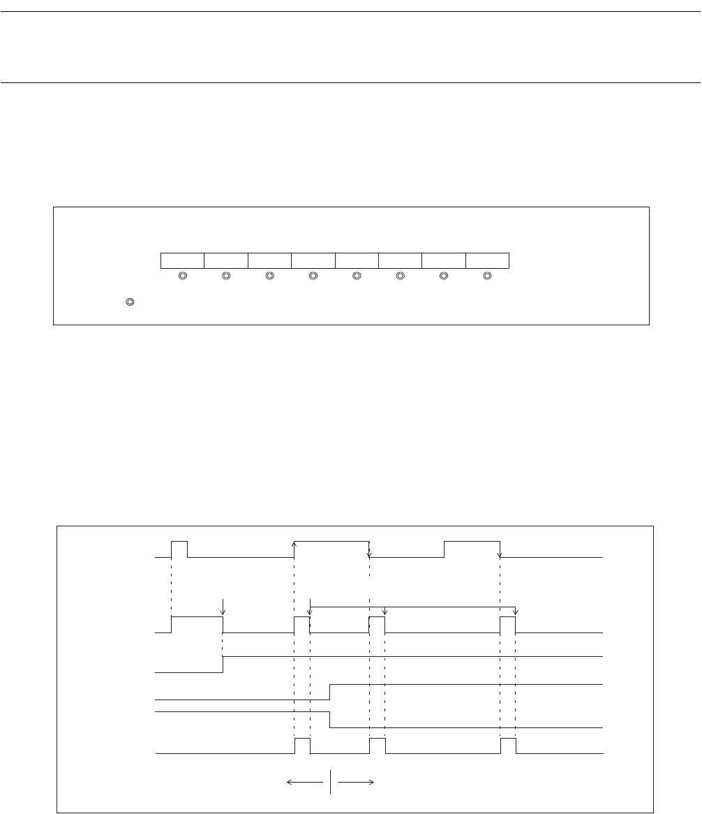
Figure 11.5-2 "External interrupt (INT1) operation" shows the operation when an external interrupt is input
to the INT1 pin.
Figure 11.5-2 External interrupt (INT1) operation
Reference:
The pin state can be read directly from the port data register (PDR4), even when used as an external
interrupt input.
EIC1 EIR1 SL11 SL10 EIE1 EIR0 SL01 SL00 EIE0
: Used bit
Bit 7 Bit 6 Bit 5 Bit 4 Bit 3 Bit 2 Bit 1 Bit 0
Input waveform
to the INT1 pin
Cleared at the same time
as the EIE1 bit is set.
Interrupt request flag bit is cleared
by the program.
EIR1 bit
EIE1 bit
SL11 bit
Rising edge set Falling edge set
IRQ1
SL10 bit


