6 SITE CONSIDERATIONS (continued)
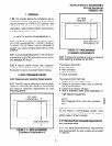
6.00 The following precautions should be adhered
to when installing telephone wiring:
GROUND 1; THIRD WIRE GRO;ND
\
TO AC POWER CORD
WARNING!
1. Never install the telephone wiring dur-
ing a lightning storm.
2. Never install the telephone jacks in wet
locations unless the jack is specifically
designed for wet locations.
3. Never touch uninsulated telephone
wires or terminals unless the telephone
line has been disconnected at the net-
work interface.
4. Use caution when installing or modify-
ing telephone lines.
7 GROUNDING REQUIREMENTS (continued)
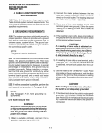
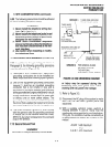
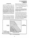
7.00 In addition to the grounding provisions in
Paragraph 5, the following grounding provisions
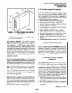
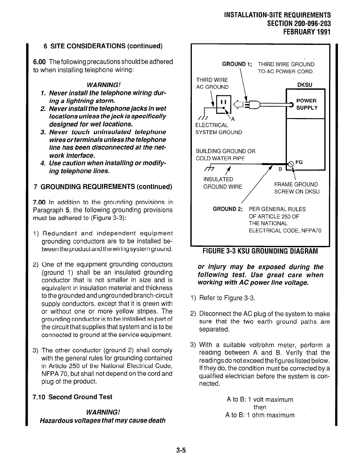
must be adhered to (Figure 3-3):
1) Redundant and independent equipment
grounding conductors are to be installed be-
tween the product and the wiring system ground.
2) One of the equipment grounding conductors
(ground 1) shall be an insulated grounding
conductor that is not smaller in size and is
equivalent in insulation material and thickness
to the grounded and ungrounded branch-circuit
supply conductors, except that it is green with
or without one or more yellow stripes. The
grounding conductor is to be installed as part of
the circuit that supplies that system and is to be
connected to ground at the service equipment.
3) The other conductor (ground 2) shall comply
with the general rules for grounding contained
in Article 250 of the National Electrical Code,
NFPA 70, but shall not depend on the cord and
plug of the product.
7.10 Second Ground Test
WARNING!
Hazardous voltages that may cause death
INSTALLATION-SITE REQUIREMENTS
SECTION 200-096-203
FEBRUARY 1991
THIRD WIRE
AC GROUND
\ \
DKSU
\
II
A+
t
A
ELECTRICAL
SYSTEM GROUND
POWER
’ SUPPLY
BUILDING GROUND OR
COLD WATER PIPE
*f
INSULATED
GROUND WIRE
FRAME GROUND
SCREW ON DKSU
GROUND 2; PER GENERAL RULES
OF ARTICLE 250 OF
THE NATIONAL
ELECTRICAL CODE, NFPA70
FIGURE 3-3 KSU GROUNDING DIAGRAM
or injury may be exposed during the
following test. Use great care when
working with AC power line voltage.
1) Refer to Figure 3-3.
2) Disconnect the AC plug of the system to make
sure that the two earth ground paths are
separated.
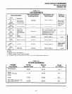
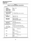
3) With a suitable volt/ohm meter, perform a
reading between A and B. Verify that the
readings do not exceed the figures listed below.
If they do, the condition must be corrected by a
qualified electrician before the system is con-
nected.
A to B: 1 volt maximum
then
A to B: 1 ohm maximum
3-5


