NOTE:
The P13 (PIOU) or W4 (PIOUS) CCITT con-
figurations are not normally used in the USA.
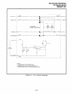
6) Programming and system testing, via the exter-
nal maintenance modem, is described in the
Remote Maintenance Procedures, Section 200-
096-400. Access to the external maintenance
modem is accomplished as follows:
If the modem is connected to adedicated
CO line, call the CO line number to estab-
lish modem communication.
If the modem is connected to a PSTU or
PESU port, call a DK CO line that can be
transferred to (or programmed to ring)
the PSTU or PESU modem port to estab-
lish modem communication.
9 VOICE MAIL/AUTO ATTENDANTOPTIONS
9.00 System Hardware Requirements
9.01 Systems may be configured to support a
Toshiba INTOUCH Digital Voice Messaging Sys-
tem, a customer-supplied voice mail messaging
system, or auto attendant.
9.02 The STRATA DK system must be equipped
with a PSTU or PESU PCB to support the voice mail
or auto attendant option. The PSTU is equipped
with eight standard telephone circuits, and the
PESU is equipped with two. A CRCU (-4 or -8)
subassembly must be installed on the PCTU or
PCTUSI PCB. The voice mail/auto attendant op-
tion may be connected to any standard telephone
circuit at the MDF block.
9.10 INTOUCH Digital Voice Messaging Sys-
tem
9.11
STRATA DK systems are designed to sup-
port the full range of features offered by the IN-
TOUCH Digital Voice Messaging System. IN-
TOUCH provides various call routing, message
handling, and information management features,
including:
l
Automated Attendant
0 Call Forward to Voice Mailbox
l
Message Waiting Indication
l
Voice Mail Control from Electronic Telephone
INSTALLATION-PERIPHERALS
SECTION 200-096-208
FEBRUARY 1991
l
System Monitoring
l
Feature Integration
.
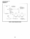
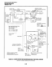
9.12 A block diagram of voice mail/auto attendant-
to-PSTU or -PESU connection is shown in Figure
8-22. See section 200-096-206for PSTU and PESU
installation.
9.13 STRATA DK/INTOUCH Programming
Considerations.
Some features of STRATA DK
system programming are unique to INTOUCH, and
are not available for customer-supplied voice mail
messaging systems. These programming features
are:
Answer (A) Tone.
The STRATA DK stations
will send an answer tone to INTOUCH when the
station answers an INTOUCH call.
Disconnect (D) Tone.
The STRATA DK sta-
tions will send a disconnect tone to INTOUCH
when the station hangs up while connected to
INTOUCH.
NOTE:
Bothansweranddisconnecttonesprovidemore
efficient INTOUCH port use. Always enable
these options. Both options are enabled by
accessing Program 31, and setting LED 15 to
ON (LEDs 16 and 17 must also be ON to allow
A and D tones).
B Tone Signals.
Stations send a recall (B) tone
to INTOUCH whenever INTOUCH answers a
transfer (camp-on) recall from a station that did
not answer an INTOUCH blind transfer. (The B
tone notifies INTOUCH that the call is a recall
and not a new call, allowing INTOUCH to re-
spond with the appropriate greeting.) For this
feature to operate, INTOUCH must be equipped
with
Version B.06
software or above; and the
DK PSTU or PESU voice mail ports must have
LEDs 19 and 20 turned
ON
in
Program 31.
9.14 INTOUCH Installation.
Use the above in-
formation in concert with Paragraphs 9.23 and 9.24
to install INTOUCH.
9.20 Customer-supplied Voice Mail Messaging
Systems
9.21 STRATA DK systems are designed to sup-
port a wide range of customer-supplied voice mail
8-15


