


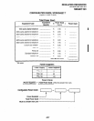
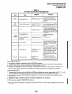


4.16 Station Port Assignments-Station
ports are
provided by the PDKU, PEKU, PSTU, and PESU
I PCBs. Each PDKU, PEKU, or PSTU PCB provides
eight station ports. The PESU provides six func-
tioning station ports, although it is allocated eight
(see Paragraph 2.60). Each PEMU uses four or
eight station ports to support TIE lines. Each of the
PCBs must have station port numbers assigned.
Record the station port numbers in the station port
numbers row on
Program
03’s record sheet. Record
m information for each slot equipped with a PDKU,
PEKU, PSTU, PESU, or PEMU PCB in the order
shown below:
1
l
PDKU and/or PEKU station ports:
Assign
station port numbers, starting with ports 00 N 07
under
slot 01,
advancing incrementally at eight
1 port numbers per PDKU and/or PEKU slot. As-
sign the numbers in numerical order until station
I
ports are assigned to all PDKU and/or PEKU
slots.
l
PSTU station ports:
Assign station port num-
bers, starting where the last station port number
stopped, advancing incrementally at eight port
numbers per PSTU slot. Assign the numbers in
numerical order until station ports are assigned
to all PSTU slots.
l
PESU station ports:
Assign station port num-
bers, starting where the last station port number
stopped, advancing incrementally at eight port
numbers per PESU slot. Assign the numbers in
numerical order until station ports are assigned
to all PESU slots.
NOTE:
PEW circuits 1 and 2 are standard telephone
ports; 3 and 4 are not used but allocated to the
PEW slot, and circuits 5 - 8 are electronic
telephone ports.
l
PEMU station ports:
Assign station port num-
bers, starting where the last station port number
stopped, advancing incrementally at four port
numbers per PEMU slot. Assign the numbers in
numerical order until station ports are assigned
to all PEMU slots.
NOTE:
If a PEMU is installed in a PCTUS 1 -controlled
DK24, only 16stationports willbe available for
INSTALLATION-CONFIGURATION
SECTION 200-096-204
FEBRUARY1991
station interface using PDKU, PEKU, PESU, 1
and PSTU PCBs. If it is installed in a PCTU (I,
2, or 3)-controlled DK24, 24 stations will be I
available, because of power supply capacity.
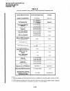
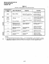
4.17 CO Line Number Assignments-Line
cir-
cuits are provided by the PCOU and PEMU PCBs.
Each PCOU provides four line circuits for CO loop
start line connections, and each PEMU provides
four line circuits to support TIE lines (each of the
PCBs must have line numbers assigned). Record
CO line numbers in the CO/TIE line numbers row
on
Program
03’s record sheet. Record information
for each slot equipped with a PCOU or PEMU in the
order shown below:
l
PCOU line numbers:
Assign CO line numbers,
starting with lines01 N 04 in the lowest numbered
PCOU slot, advancing incrementally at four line
numbers per PCOU slot. Assign the numbers in
numerical order until CO lines are assigned to all
PCOU slots.
l
PEMU line numbers:
Assign TIE line numbers,
starting with the next line above the highest
PCOU line, advancing incrementally at four line
numbers per PEMU slot.
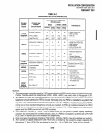
4.18 PCB Additions-To
add PCBs to an existing
installation, assign the PCBs in the order described
above. Start with the lowest numbered empty slot
and continue without skipping a slot until all PCBs
are assigned. Then, using the guidelines described
above, record the new PCB configuration informa-
tion on the record sheet for
Program 03.
NOTE:
PEMU PCBs should be first moved to higher
slot numbers to create the necessary number
of empty slots for additions. Be sure to repro-
gram for the new PEMU positions, including
new station number assignments for the
PEMU(s).
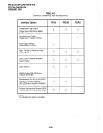
4.20 Door Phone Hardware Configuration Notes
l
A maximum of 12 door phones are allowed per
system with PCTU (1, 2, or 3) and nine with
PCTUSI. Each door phone must be connected
to an HDCB.
l
A maximum of three door phones may be con-
4-25