


INSTALLATION-PCB
SECTION 200-096-206
FEBRUARY 1991
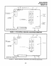
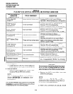
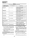
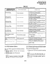
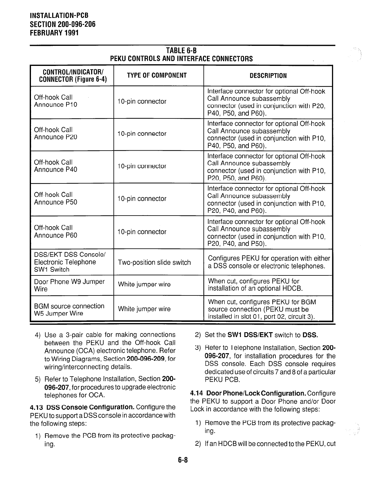
TABLE 6-B
PEKU CONTROLS AND INTERFACE CONNECTORS
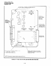
CONTROL/INDICATOR/
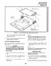
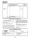
CONNECTOR (Figure 6-4)
TYPE OF COMPONENT DESCRIPTION
Off-hook Call
Announce PlO
1 O-pin connector
Interface connector for optional Off-hook
Call Announce subassembly
connector (used in conjunction with P20,
P40, P50, and P60).
Off-hook Call
Announce P20
1 O-pin connector
Off-hook Call
Announce P40
1 O-pin connector
Off-hook Call
Announce P50
1 O-pin connector
Interface connector for optional Off-hook
Call Announce subassembly
connector (used in conjunction with PlO,
P40, P50, and P60).
Interface connector for optional Off-hook
Call Announce subassembly
connector (used in conjunction with PlO,
P20, P50, and P60).
Interface connector for optional Off-hook
Call Announce subassembly
connector (used in conjunction with PlO,
P20, P40, and P60).
Off-hook Call
Announce P60
1 O-pin connector
Interface connector for optional Off-hook
Call Announce subassembly
connector (used in conjunction with PlO,
P20, P40, and P50).
DSSEKT DSS Console/
Electronic Telephone Two-position slide switch
Configures PEKU for operation with either
SW1 Switch
a DSS console or electronic telephones.
Door Phone W9 Jumper
Wire
White jumper wire
When cut, configures PEKU for
installation of an optional HDCB.
BGM source connection
W5 Jumper Wire
White jumper wire
When cut, configures PEKU for BGM
source connection (PEKU must be
installed in slot 01, port 02, circuit 3).
.
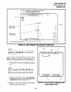
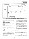
4) Use a 3-pair cable for making connections
2)
Set the
SW1 DSS/EKT
switch to
DSS.
between the PEKU and the Off-hook Call
Announce (OCA) electronic telephone. Refer
to Wiring Diagrams, Section 200-096-209, for
wiring/interconnecting details.
5) Refer to Telephone Installation, Section 200-
096-207, for procedures to upgrade electronic
telephones for OCA.
4.13 DSS Console Configuration.
Configure the
PEKU to support a DSSconsole in accordance with
the following steps:
1) Remove the PCB from its protective packag-
ing.
3) Refer to Telephone Installation, Section 200-
096-207, for installation procedures for the
DSS console. Each DSS console requires
dedicated use of circuits 7 and 8 of a oarticular
PEKU PCB.
4.14 Door Phone/LockConfiguration.
Configure
the PEKU to support a Door Phone and/or Door
Lock in accordance with the following steps:
1) Remove the PCB from its protective packag-
ing.
2) If an HDCB will be connected to the PEKU, cut
6-8