


Four PCOU PCBs
One PEMU PCB
Six PEKU PCBs
One PSTU PCB
One PIOU PCB
One EOCU subassembly
One CRCU subassembly
l
A total of 13 universal slots (one for each of
the PCBs with the prefix “P”) will be used in
this DK96 system. It is working with 18 tele-
phone lines and 48 station devices so it is
quite a large system. Another five electronic
telephones could be added without requiring
use of another universal slot.
2.70 Miscellaneous
2.71
Other hardware items may be needed in a
particular system configuration. These include the
DPFT power failure transfer unit, used to connect
CO lines to standard telephones in the event of a
power outage; the HESB speaker/amplifier, which
may interface with an digital or electronic telephone;
the HHEU headset interface, which may be re-
quired to hook up an HESB or a headset to a digital
or 6500-series electronic telephone; an HESC-65
cable, to connect the HESB to a 6500-series
electronic telephone; a PBTC-3M cable, for con-
nection to reserve batteries or a PPTC connector
for an SMDR printer, TTY, or remote maintenance
terminal interface. More details on these miscella-
neous items can be found in Table 4-F, the General
Description, and other Installation chapters.
I
NOTE:
An HESC-65A only is required to connect a
digital telephone to an HESB; this cable can
also be used with 6500-series electronic
telephones.
2.80 Ports
2.81 Interfaces to each of some devices (such as
telephones) in the STRATA DK system can be
referred to as ports. Therefore, a PEKU, PDKU,
I PSTU, and PESU PCB can be said to have station
ports (see Note 2). STRATA DK system program-
ming uses port numbers to identify which device
will be equipped with desired features or operation.
INSTALLATION-CONFIGURATION
SECTION 200-096-204
FEBRUARY1991
The first port number is 00 and can continue up to
95 with a PCTU (1,2, or 3) PCB and up Jo 23 with
a PCTUS PCB. Port 00 is usually intercom station 200, 1
and is designated as the primary system attendant
station. Intercom numbering can becompletely flexibly
assigned, but is best left to the consecutive standard
numbering of 200 N 295 with PCTU (1, 2, and 3) and 1
200 N 223 with PCTUSl . User guides are written using
this standard plan, and LCD digital and electronic 1
telephone busy fields will be meaningful only if the last
two digits of the intercom number are consecutive,
starting with 00.
NOTES:
1. Each PEMU uses four station ports and four
CO lines; however, if the PEMU is installed in
a DK24 with a PCTUSl PCB, on/y 16 station
ports are available for station interface using
PEKU, PSTU, or PESU PCBs, because the
PCTUSassigns, eightstationports to the PEMU
PCB.
2. Each PEW provides two standard and four
electronic telephone ports for a total of six
stationports; however, two nonfunctioningpotis
(circuits 3 and 4) are automatically assigned to
the PESU so a total of eight station ports are
allocated to each PESU PCB installed.
2.90 CO Lines
2.91 Telephone network CO lines interface to the
STRATA DK PCOU PCB. Four circuits are provided by
each PCOU. These circuits are identified as CO lines
in DK system software and are not considered as ports
but are in addition to ports when considering total
system station and line capacity.
NOTE:
Each PEMUuses four CO lines in system software
as well as four PCTU 1,2,3 or eight PCTUS ports
in system software.
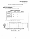
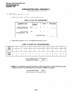
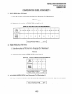
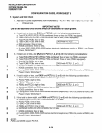
3 WORKSHEETS
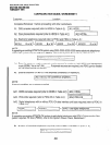
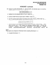
3.00 To use a methodical step-by-step procedure to
configure a system, worksheets are provided in this
section. Use of these worksheets will automatically
consider all of the various factors.
4-7