


the
W9
Door Phone jumper wire on the PEKU
PCB.
3) Refer to Telephone Installation, Section 200-
096-207, for installation procedures for the
HDCB, control box and associated door
phones (MDFBs).
4) Each HDCB requires dedicated use of circuit
5 of a particular PEKU PCB.
4.15 Background Music Configuration.
Config-
ure the PEKU to support a background music
source in accordance with the following steps:
1) Remove the PCB from its protective packag-
ing.
2) Cut the
W5
(BGM) jumper wire on the PEKU
PCB.
3) Refer to Peripherals Installation, Section 200-
096-208, for installation procedures for BGM
connection.
NOTE:
The PEKU must be installed in slot 01 to allow
a
4)
BGM connection.
In
Program 10-2,
set
LED
09 ON to enable
the PEKU (port 02) BGM source to be sent to
electronic telephone speakers and/or PIOU,
PIOUS, PEPU PCBs.
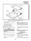
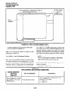
4.20 PEKU Installation Procedures
4.21 Install the PEKU in accordance with the fol-
lowing steps:
1)
2)
Remove the PCB from its protective packag-
ing.
Ensure the PEKU has been configured for the
appropriate hardware options (refer to Para-
graph 4.10).
NOTE:
Ensure the PEKU’s component side is facing
right when installing it in the KSU .
3) Insert the PEKU into the appropriate slot (refer
to Paragraph 2.12), and apply firm, even
4)
INSTALLATION-PCB
SECTION 200-096-206
FEBRUARY 1991
pressure to ensure proper mating of connec-
tors.
.
After installing the PEKU, gently pull the PCB
outward. If the connectors are properly mated,
a slight resistance will be felt.
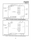
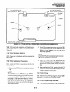
4.30 PEKU Wiring
4.31
Refer to PEKU Wiring Diagrams, Section
200-096-290, for wiring/interconnecting details.
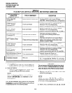
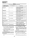
4.40 PEKU Programming Overview
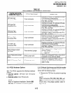
4.41
The following parameters may be specified,
through programming, for the PEKU:
Program 03
l
Specify code 21 to indicate a station line PEKU.
l
Specify code 22 to indicate a PEKU configured
for OCA.
l
Specify code 23 to indicate a PEKU configured
for a DSS console.
l
Specify code 24 to indicate a PEKU configured
for OCA and a DSS console.
l
Door phones do not require a special code.
Program 1 O-2
l
Used for BGM connection.
Programs 28 and 29
l
Used for DSS assignments.
Programs 77-1 and 77-2
l
Used for HDCB assignments,
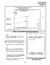
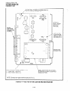
5 STANDARD TELEPHONE INTERFACE
UNIT (PSTU)
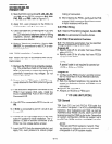
5.00 General
5.01
The Standard Telephone Unit (PSTU) pro-
vides an interface between standard telephones or
two-wire devices and the system. Each PSTU PCB
adds eight standard telephone lines to the system.
There is no limit, other than the station size con-
straints of the PCTU PCB, to the number of PSTU
PCBs that can be installed in the system.
NOTE:
For the system to recognize the DTMF tones
generated by a standard telephone (or any
other device connected to a PSTU port), a
DTMF Receiver Unit (CRCU-4 or CRCU-8)
6-9