


INSTALLATION-KSU
SECTION 200-096-205
FEBRUARY 1991
3 POWER SUPPLY TEST PROCEDURE
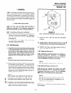
3.00 Perform the power supply test procedure
with all PCBs removed from the KSU.
NOTE:
Refer to System Description, Section 200-096-
202, for illustrations and descriptions of KSU
controls and indicators.
1) Plug the AC power cable into the AC IN con-
nector and to the AC wall socket.
NOTE:
The DK24 power cable is permanent/y con-
nected to the power supply.
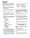
2) Lightly press all power supply circuit breakers
to ensure they have not accidentally opened
during shipment.
3) Set the power supply power switch to ON.
Ensure that the power supply indicators light as
follows:
. DK24:
l
POWER indicator
l
-24V indicator
l
+5V indicator
l
-5V indicator
l
-24V, W V, (circuit breakers)
. DK56:
l
POWER indicator
l
+5V indicator
. -5V indicator
l
-24V, W V, (circuit breakers)
. DK96:
l
POWER indicator
l
-5V indicator
l
+5V, indicator
l
+5V, indicator
l
-24V, W V,(circuit breakers)
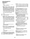
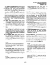
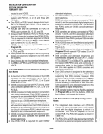
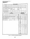
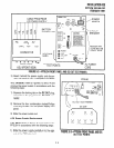
4) Using a multimeter (set to the appropriate range),
measure the voltages at the pins of the DC OUT
connector for DK56/DK96 or the PI backplane
connector for DK24 as shown in Figures 5-2,5-
3, or 5-4. Ensure that the voltages fall within the
ranges specified. If a measured voltage falls
outside of the acceptable range, remove the
DC power plug from the power supply DC OUT
connector (DK56/96) or PI backplane con-
nectar (DK24) and measure again. If a meas-
ured voltage is still unacceptable, rep!ace the
power supply (refer to Paragraph 4).
DC Voltage Range Specifications
-24V: -26.3 - -27.0
-5V:
-4.5 - -5.5
+5V: +4.5 - +5.5
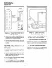
3.01 To test the power supply voltages with all
circuit boards installed, install the circuit boards
and then use the procedure in Paragraph 3.00 for
the PPSU56/96, but follow the four steps below to
test the PPSU24.
1) Loosen the four screws holding the panel on
the back of the KSU.
2) Lift the panel up and pull it off of the KSU.
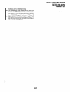
3) On the lower left side of the backplane PCB
(PMB-824), the test points for the various volt-
ages are marked. Refer to Figure 5-5.
4) Using the multimeter (set to the appropriate
range), measure the voltages at the desig-
nated test points.
NOTE:
The multimeter test probes must have sharp
tips to penetrate solder mask on backplane
PCB.
4 POWER SUPPLY REMOVAL AND
REPLACEMENT
4.00 The following paragraphs provide procedures
necessary to remove and replace faulty power
supplies.
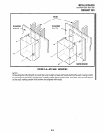
4.10 Power Supply Removal
4.11 DK24. Refer to Figure 5-2 and remove the
power supply in accordance with the following
steps:
1) Remove screws (2) on right side of the KSU.
2) Slide the power supply out and gently remove
it from the KSU.
5-2