


INSTALLATION-CONFIGURATION
SECTION 200-096-204
FEBRUARY1991
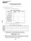
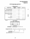
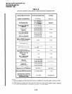
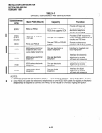
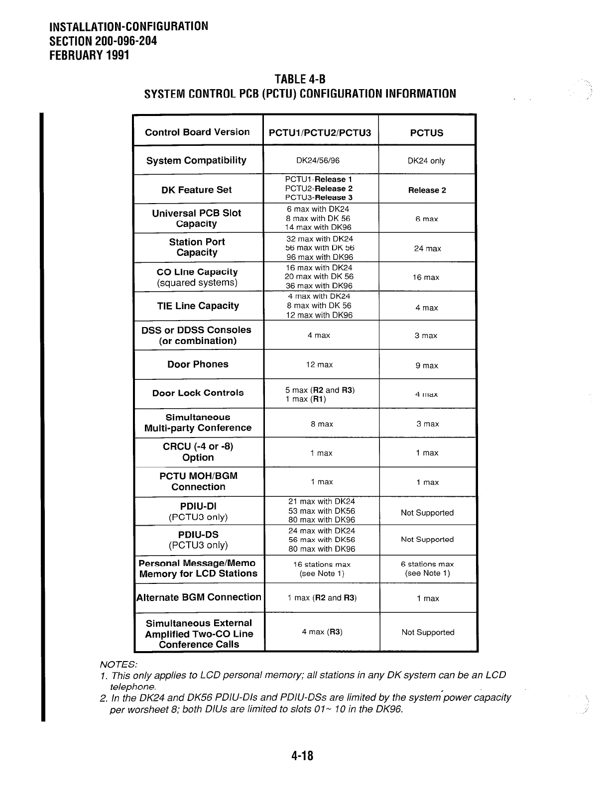
TABLE4-B
SYSTEMCONTROLPCB(PCTU)CONFlGURATlONlNFORMATlON
Control Board Version
PCTUl/PCTUP/PCTU3
PCTUS
System Compatibility
DK24/56/96
DK24 only
PCTUI -Release 1
DK Feature Set
PCTU2-Release 2
Release 2
PCTU3-Release 3
Universal PCB Slot
Capacity
Station Port
Capacity
CO Line Capacity
(squared systems)
TIE Line Capacity
DSS or DDSS Consoles
(or combination)
6 max with DK24
8 max with DK 56
14 max with DK96
32 max with DK24
56 max with DK 56
96 max with DK96
16 max with DK24
20 max with DK 56
36 max with DK96
4 max with DK24
8 max with DK 56
12 max with DK96
4 max
6 max
24 max
16 max
4 max
3 max
Door Phones
12 max 9 max
Door Lock Controls
I
5 max (R2 and R3)
1 max (Rl)
4 max
Simultaneous
Multi-party Conference
I
8 max 3 max
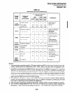
CRCU (-4 or -8)
Option
I
1 max
PCTU MOH/BGM
Connection
I
1 max
I
1 max
PDIU-DI
(PCTU3 only)
PDIU-DS
(PCTU3 only)
21 max with DK24
53 max with DK56
80 max with DK96
24 max with DK24
56 max with DK56
80 max with DK96
Not Supported
Not Supported
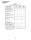
Personal Message/Memo
Memory for LCD Stations
Alternate BGM Connection
Simultaneous External
Amplified Two-CO Line
Conference Calls
16 stations max
6 stations max
(see Note 1)
(see Note 1)
1 max (R2 and R3) 1 max
4 max (R3)
Not Supported
NOTES:
1. This only applies to LCD personal memory; all stations in any DK system can be an LCD
telephone.
2. In the DK24 and DK56 PDIU-Dls and PDIU-DSs are limited by the systempower capacity
per worsheet 8; both DlUs are limited to slots 0 1- IO in the DK96.
.’
4-18