INSTALLATION-CONFIGURATION
SECTION 200-096-204
FEBRUARY 1991
CONFIGURATION GUIDE, WORKSHEET 4
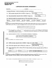
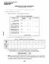
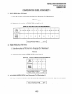
C. PCOU PCBs (four CO lines)
1. Enter the number of CO lines required from Paragraph C of Worksheet 1.
CO lines
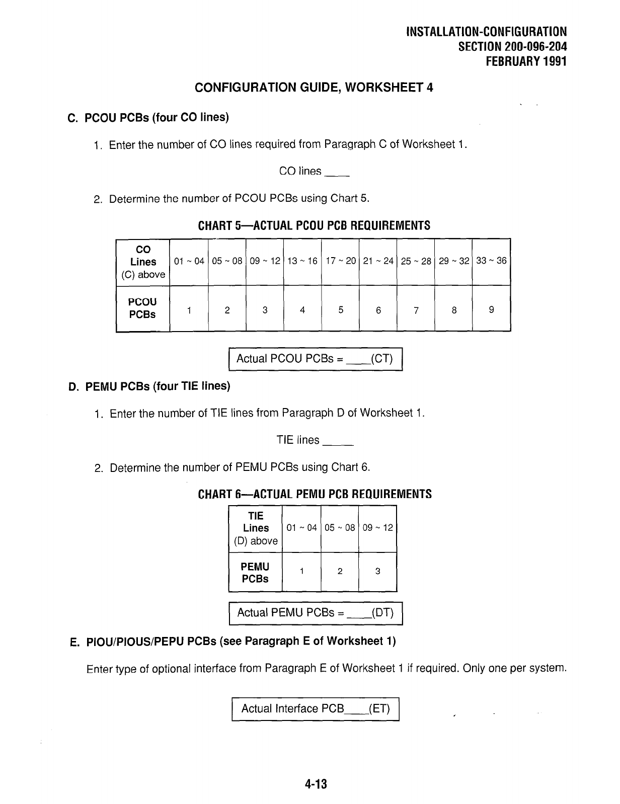
2. Determine the number of PCOU PCBs using Chart 5.
CHART 5-ACTUAL PCOU PCB REQUIREMENTS
co
Lines
01-04 05-08 09-12 13-16 17-20
21-24 25-28 29-32 33-36
(C) above
PCOU
PCBs
1 2 3 4 5 6 7 8 9
Actual PCOU PCBs =
-.Ac-u (
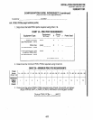
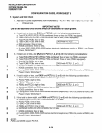
D. PEMU PCBs (four TIE lines)
1. Enter the number of TIE lines from Paragraph D of Worksheet 1.
TIE lines
2. Determine the number of PEMU PCBs using Chart 6.
CHART 6-ACTUAL PEMU PCB REQUIREMENTS
TIE
Lines
01 -04 05-08 09-12
(D) above
PEMU
1 2 3
PCBs
I
Actual PEMU PCBs =
-..Aw )
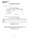
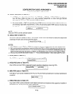
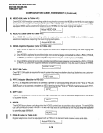
E. PIOU/PIOUS/PEPU PCBs (see Paragraph E of Worksheet 1)
Enter type of optional interface from Paragraph E of Worksheet 1 if required. Only one per system.
Actual Interface PCB
-.wW
I
4-13


