


f
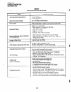
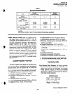
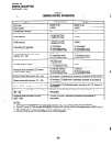
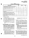
lengths, network requirements, and system tone
patterns are summarized in Tables E, F, and G,
respectively).
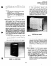
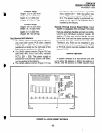
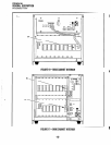
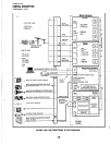
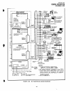
The system can have several options config-
ured, as illustrated in the functional block dia-
gram (Figures 18A and 18B).
As represented in the functional block dia-
gram, the system’s cabinet contains a power
supply and printed circuit boards appropriate to
the user’s configuration. PCBs include the com-
mon control unit (PCTU2, PCTU3, or PCTUS),
DTMF receiver subassembly (CRCU-4 or CRCU-
8), option interface unit (PIOU, PIOUS, or
PEPU), remote maintenance modem subassem-
bly (IMDU), CO line unit (PCOU), E & M TIE line
unit (PEMU), digital telephone interface unit
(PDKU)t, electronic telephone interface unit
(PEKU), off-hook call announce subassembly
(EOCU), standard telephone interface unit
(PSTU), and a combination electronic/standard
telephone interface unit (PESU).
!iD
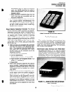
Printed Circuit Boards
Most STRATA DK system hardware options
are integrated within the system cabinet. Each
major PCB measures 7.5 x 5.5 inches (190 x 140
mm) and mounts in a PCB slot in the shelf with a
44-pin backplane connector.
PCB external connections are made to the
Main Distribution Frame (MDF) using the follow-
ing industry-standard connectors:
l
25pair Amphenol Female: Connects digital
telephones, electronic telephones, standard
telephones, and most peripherals.
l
Modular: Connects CO lines, E & M TIE
lines, station message detail recording port
(W-232), and maintenance port (RS-232).
l
Terminals: MOH and some peripherals.
The following list includes every PCB that can
be installed in the key service unit. Each PCB’s
function is described, along with applicable con-
figuration and connection details.
Common Control Unit (PCTU): The PCTU is
the system’s controller PCB, and must be
STRATA DK
GENERALDESCRIPTION
DECEMBER1990
installed for the system to operate. It contains
the system’s main 16-bit, 68000-type micro-
-processor and microprocessor bus, battery-
protected memory circuits, time switch logic,
conference logic, and system tones. The
PCTU also has a music-on-hold/background
music source interface, and connectors to
mount an optional DTMF receiver PCB
(CRCU) for DISA, TIE lines, standard tele-
phones and peripherals. There are three ver-
sions of PCTU PCBs available: PCTUS,
PCTU2, and PCTU3. PCTUS and PCTU2 pro-
vide Release 2 features; PCTU3 provides
Releases 2 and 3 features. See Table H for
PCTU comparison and compatibility.
DTMF Receiver Subassembly (CRCU): An
optional DTMF receiver PCB mounts onto the
PCTU piggy-back style. It translates DTMF
signals from direct inward system access
(DISA) CO lines, TIE lines, standard tele-
phones or peripheral devices to data signals
for the system.
l
One CRCU option must be installed for the
system to receive DTMF dialing. Both 4-
and 8-circuit CRCUs are available (CRCU-
4 and CRCU-8).
l
CRCU DTMF receiver circuits are shared
by users, i.e. a receiver is seized for dial-
ing and then released for the next call.
Option Interface Unit (PIOU): The PIOU pro-
vides a circuit interface with the peripheral
options, including external paging functions,
alarm interface, SMDR, and remote mainte-
nance. Table I shows details of each feature.
Simplified Option Interface Unit (PIOUS): A
reduced model of the PIOU, the PIOUS pro-
vides an interface with the peripheral options
shown in Table I.
External Page Interface Unit (PEPU): Also a
reduced model of the PIOU, the PEPU pro-
vides a circuit interface with the peripheral
options shown in Table I.
Remote Maintenance fvlodem’ Subassembly
(IMDU): An optional built-in modem provides
the system with a link to off-site programming
-17-