INSTALLATION-CONFIGURATION
SECTION 200-096-204
FEBRUARY 1991
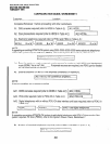
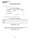
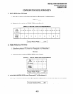
CONFlGURJiTlON GUIDE, WORKSHEET 3
(PSTWPESU PCB requirements)
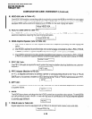
B. PSTU PCBs (eight station ports)
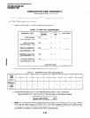
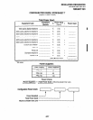
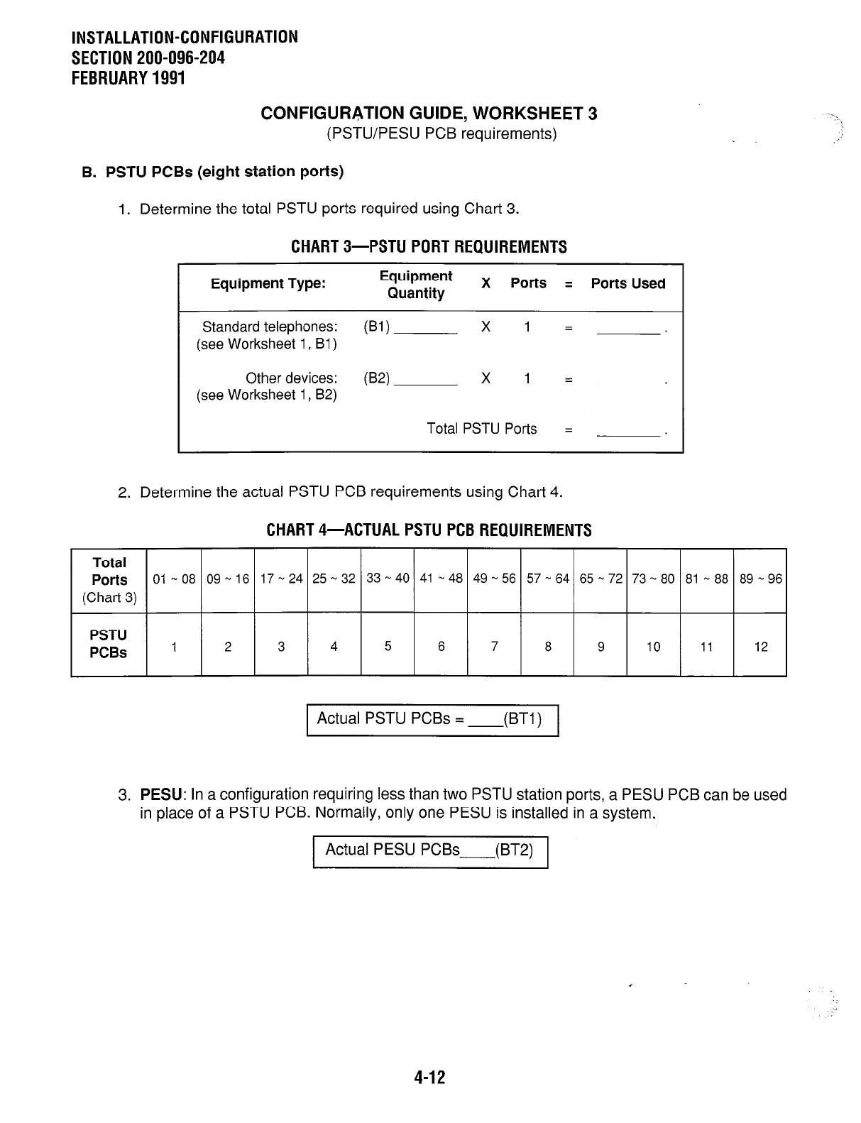
1. Determine the total PSTU ports required using Chart 3.
CHART 3-PSTU PORT REQUIREMENTS
Equipment Type:
Equipment
Quantity
X Ports = Ports Used
Standard telephones:
WI
x 1 =
(see Worksheet 1, Bl)
Other devices:
WI
x 1 =
(see Worksheet 1, B2)
Total PSTU Ports =
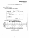
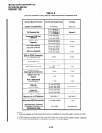
2. Determine the actual PSTU PCB requirements using Chart 4.
CHART 4-ACTUAL PSTU PCB REQUIREMENTS
Total
Ports
(Chart 3)
PSTU
PCBs
1 Actual PSTU PCBs = (BT1)I
81 - 88 89 - 96
12
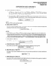
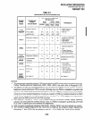
3. PESU:
In a configuration requiring less than two PSTU station ports, a PESU PCB can be used
in place of a PSTU PCB. Normally, only one PESU is installed in a system.
Actual PESU
PCBs
-(BT.9
4-12


