


INSTALLATION-CONFIGURATION
SECTION 200-096-204
FEBRUARY 1991
CONFIGURATION GUIDE, WORKSHEET 2
(PEKLVPDKU PCB requirements)
Customer
Location
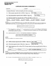
B. PEKU PCBs (eight station ports)
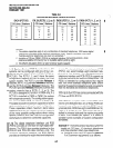
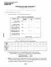
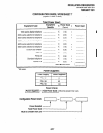
1. Determine the total PEKU ports required using Chart 1.
CHART I-PEKU PORT REQUIREMENTS
Equipment Type:
Equipment
Quantity
x (Ports/
per)
= Ports Used
DSS consoles:
(Al)
x 2 =
(see Worksheet 1, Al)
HDCB controllers:
VW
x 1 =
(see Worksheet 1, A2)
Electronic telephones:
(A3)
x 1 =
(see Worksheet 1, A3)
BGM/MOH separation:
(A4)
x 1 =
(see Worksheet 1, A4)
Conference amplifiers:
VW
x 2 =
(see Worksheet 1, A5)
Total PEKU Ports =
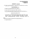
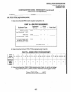
2. Determine the minimum PEKU PCBs required using Chart 2.
CHART P-MINIMUM PEKU PCB REQUIREMENTS
-r
01-08 09-16
17-24 25-32 33-40 41-48 49-56 57-64
3
4 5 6 7
8
65 - 72 73 - 80
I
9 IO
81 - 88 89 - 96
11 12
3. Determine the actual PEKU PCBs required using Charts 1 and 2 as follows:
Actual PEKUs (AT) = (Am) or (Al) or (A2) whichever is the largest number.
Actual PEKU PCBs =
-..-.Jv 1
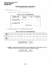
4. PESU:
In a configuration that requires less than five electronic telephone station-ports, a PESU
PCB may be used in place of a PEKU PCB. The PESU supports HDCBs and a BGM source .:.
connection as well as electronic telephones. It does not support a DSS console. Normally, only .I’
one PESU is installed in a system (see PSTU, Worksheet 3).
4-l 0