


INSTALLATION-KSU
SECTION 200-096-205
FEBRUARY 1991
DC OUT
+SJ,
0 0’
-5V,
-24Vj
-24V2
0 0
-24V3
0
PPSU96
(”
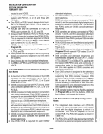
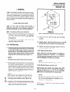
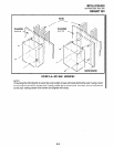
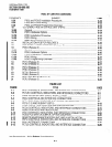
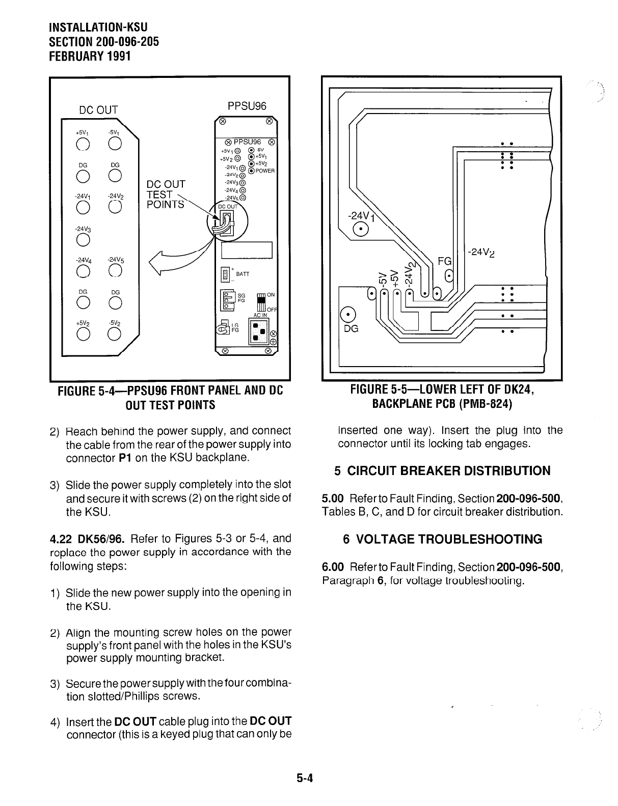
FIGURE 5-4-PPSU96 FRONT PANEL AND DC
OUT TEST POINTS
2) Reach behind the power supply, and connect
the cable from the rear of the power supply into
connector Pl on the KSU backplane.
3) Slide the power supply completely into the slot
and secure it with screws (2) on the right side of
the KSU.
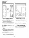
4.22 DK56196. Refer to Figures 5-3 or 5-4, and
replace the power supply in accordance with the
following steps:
1) Slide the new power supply into the opening in
the KSU.
2) Align the mounting screw holes on the power
supply’s front panel with the holes in the KSU’s
power supply mounting bracket.
3) Secure the power supply with the four combina-
tion slotted/Phillips screws.
4) Insert the DC OUT cable plug into the DC OUT
connector (this is a keyed plug that can only be
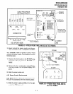
FIGURE 5-5-LOWER LEFT OF DK24,
BACKPLANE PCB (PMB-824)
inserted one way). Insert the plug into the
connector until its locking tab engages.
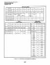
5 CIRCUIT BREAKER DISTRIBUTION
5.00 Referto Fault Finding, Section 200-096-500,
Tables B, C, and D for circuit breaker distribution.
6 VOLTAGE TROUBLESHOOTING
6.00 Refer to Fault Finding, Section 200-096-500,
Paragraph 6, for voltage troubleshooting.
5-4