


INSTALLATION-SYSTEM DESCRIPTION
SECTION 200-096-202
FEBRUARY1991
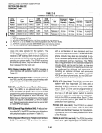
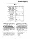
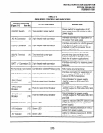
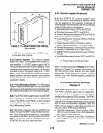
TABLE2-E
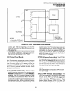
DK56MODELCONTROLSANDlNDlCATORS
CONTROL/INDICATOR
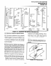
Figure 2-12
Item No.)
TYPE OF COMPONENT
DESCRIPTION
ON/OFF Switch
(1) Two-position rocker switch
Power switch for application of AC
input power from wall socket to KSU
power supply
AC IN Connector (2) 3-pin keyed male connector
Interface connector for application of
AC power from wall outlet
Interface connector for LG/FG ground
LG/FG Connector (3) 2-pin keyed male connector
strap (ground strap must remain
installed in LG/FG connector for all
system applications)
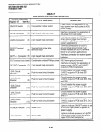
SG/FG Terminal
Block
(4) Two-terminal screw-type
terminal block
Terminal connections for SG/FG
ground strap (ground strap must
remain installed on SG/FG terminal
block for all system applications)
BATT +/- Connector (5) 2-pin keyed male connector
Interface connector for reserve power
batteries
-G Terminal (not shown) Combination slotted/Phillips screw KSU frame ground terminal
DC OUT Connector (7) 7-pin keyed male connector
Interface connector for application of
power supply +5VDC and -24VDC
outputs to KSU’s backplane
-24V1 Circuit
Breaker
Circuit breaker for power supply
(8)
Push-to-reset circuit breaker
-24VDC output to PCB slots SO1
and SO2
-24V2 Circuit
Breaker
Circuit breaker for power supply
(9)
Push-to-reset circuit breaker
-24VDC output to PCB slots S03, S04,
and SO5
-24V3 Circuit
Breaker
Circuit breaker for power supply
(10)
Push-to-reset circuit breaker
-24VDC output to PCB slots S06, S07,
and SO8
POWER Indicator (11) Green LED
Lights to indicate ON/OFF switch is sei
to ON (AC input power is applied to
power supply)
t5V Indicator
(12) Green LED
Lights to indicate presence of +5VDC
output from power supply
-5V Indicator
(13) Green LED
Lights to indicate presence of -5VDC
output from power supply
2-15