


INSTALLATION-SITE REQUIREMENTS
SECTION 200-096-203
FEBRUARY1991
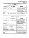
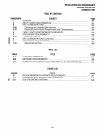
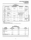
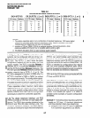
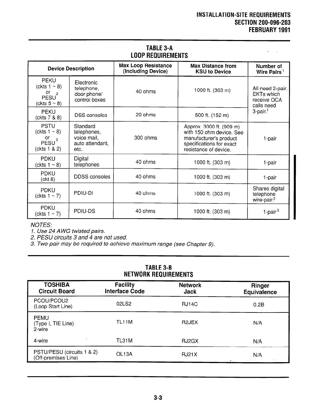
TABLE3-A
LOOPREQUIREMENTS
Device Description
PEKU
(ckts 1 w 8)
Electronic
P&J’
telephone,
door phone/
(ckts 5 N 8)
control boxes
PEKU
(ckts 7 & 8)
DSS consoles
Max Loop Resistance
Max Distance from
(Including Device) KSU to Device
40 ohms
1000 ft. (303 m)
20 ohms
500 ft. (152 m)
Number of
Wire Pairs 1
All need 2-pair.
EKTs which
receive OCA
calls need
3-pair.’
PSTU
(ckts 1 * 8)
P&J 2
(ckts 1 & 2)
PDKU
(ckts 1 N 8)
PDKU
(ckt 8)
PDKU
(ckts 1 N 7)
PDKU
(ckts 1 w 7)
Standard
telephones,
voice mail,
auto attendant,
etc.
Digital
telephones
DDSS consoles
PDIU-DI
PDIU-DS
300 ohms
40 ohms
40 ohms
40 ohms
40 ohms
Approx. 3000 ft. (909 m)
with 150 ohm device. See
manufacturer’s product 1 -pair
specifications for exact
resistance of device.
1000 ft. (303 m)
1 -pair
1000 ft. (303 m)
1 -pair
Shares digital
1000 ft. (303 m)
telephone
wire-pair?
1000 ft. (303 m) 1 -pair3
NOTES:
1. Use 24 A WG twisted pairs.
2. PESU circuits 3 and 4 are not used.
3. Two-pair may be required to achieve maximum range (see Chapter 9).
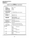
TABLE3-B
NETWORKREQUIREMENTS
TOSHIBA
Circuit Board
Pcou/Pcou2
(Loop Start Line)
Facility
Interface Code
02LS2
Network
Jack
RJl4C
Ringer
Equivalence
0.26
PEMU
(Type I, TIE Line)
2-wire
TLllM
R2JEX N/A
4-wire
PSTU/PESU (circuits 1 & 2)
(Off-premises Line)
OLl3A RJ21 X
N/A
3-3