


to a hunting sequence, starting with the Iow-
est port hunting to the next highest port, etc.
The last hunt should be to an attendant.
l
Program
35: LEDs 01 and 02 must be ON
for stations to receive the message indica-
tion (MW LED flashing) from a VM device.
l
Program
36: Set fixed call forward to VM/
AA port per customer requirements.
l
Program
37: Set the timer for the VM/AA
ports to 22 seconds minimum to allow call
forward no answer to work on VM transferred
calls.
l
Program
39: Set the MW/FL, CFF, RDL
and SDS buttons on the electronic tele-
phones that will be used to communicate
with the VM/AA device.
l
Programs 81
N 89: Verify that the ringing
assignments to the VM/AA devices are set
per customer requirements.
l
Programs
16,40,41,45 N 48 and 50 N 56:
Verify that outgoing CO line access is al-
lowed on VM ports to allow the VM/AA beeper
notification feature to operate.
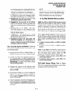
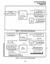
9.25 Voice Mail System Installation.
Install the
voice mail messaging system in accordance with
the following steps:
1) Ensure that the PSTU or PESU PCB is in-
stalled in the system per Section 200-096-206.
2) Connect the voice mail messaging system to
the selected PSTU or PESU standard tele-
phone port (refer to Wiring Diagrams, Section
200-096-290, for PSTU and PESU wiring/
interconnecting details).
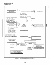
3) Program the system for the required voice
mail messaging features (refer to Paragraphs
9.13
and 9.22).
4) Ensure that a CRCU (-4 or -8) is installed on
the PCTU or PCTUSl PCB, and verify that the
PCTU code in
Program 03
is for CRCU op-
eration as required.
5) Perform additional voice mail messaging sys-
tem programming as applicable (refer to cus-
tomer-supplied installation/programming
manuals).
INSTALLATION-PERIPHERALS
SECTION 200-096-208
FEBRUARY 1991
NOTE:
Some voice mail devices may ring tcip when
called; in
this
case, set the ring voltage jumper
to L (low position) on the PEW or PSTUZ
PCB connected to the voice mail device.
10 ALARM SENSOR INSTALLATION
10.00
The PIOU or PIOUS PCB provides a circuit
that can be set to detect a relay open or closed
condition from a facility alarm system. When the
sensor is activated, all electronic telephones will
sound an alarm signal. The electronic telephone
alarm signal can be reset by any electronic tele-
phone with an alarm reset button (see
Program 39).
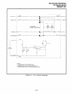
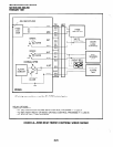
10.01 Alarm Sensor Options.
Jumper plug
PI2
on the PIOU is used to set the alarm sensor to
detect an open or closed condition from the facility
alarm system. Set
PI2
as follows (refer to Figure
8-23) :
l
To detect a closed condition, set
PI 2
to the N.O.
position.
l
To detect an open condition, set
PI 2
to the NC.
position.
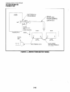
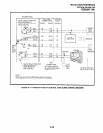
10.02 Jumper
W3
on the PIOUS is used to set the
alarm sensor to detect an open or closed condition
from the facility alarm system. Solder the W3
jumper wire as follows (refer to Figure 8-22):
l
To detect a closed condition, solder W3 to the
normal open position.
l
To detect an open condition, solder W3 to the
normal closed position.
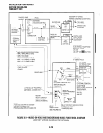
10.03 Alarm Sensor Wiring.
Refer to Figure
8-23, and connect the facility alarm system relay
contacts to the PIOU/PIOUS PCB.
8-17