


4.20 Digital Telephone Connections
4.21
Wiring Diagrams, Section 200-096-209,
provide point-to-point MDF wiring diagrams for
connecting digital telephones, DDSS consoles,
and PDIU-DSs to STRATA DK systems. Refer to
Programming Procedures, Section 200-096-300,
for programming requirements and procedures.
The following paragraphs provide general re-
quirements for telephone installation.
WARNING!
1. Never install the telephone wiring dur-
ing a lightning storm.
2. Never install the telephone jacks in
wet locations unless the jack is spe-
cifically designed for wet locations.
3. Never touch uninsulated telephone
wires or terminals unless the telephone
line has been disconnected at the net-
work interface.
4. Use caution when installing or modify-
ing telephone lines.
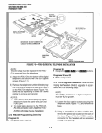
4.22 Digital telephonesareconnected to the PDKU
(via the MDF) with standard twisted-pair jacketed
telephone cable. Single-pair wiring is sufficient
unless the system must operate on reserve power
or in the case of a digital telephone with a PDIU-DI.
In these cases, two-pair wiring should be used for
extra power (see Section 200-096-209 for details).
To accommodate the digital telephone line cord,
the cable should be terminated in a modular sta-
tion connector block (RJ-1 1 ) at the station location.
The standard modular digital telephone cord length
is 7 feet (the maximum allowed length is 25 feet).
4.23 The overall length of the station cable (single
pair) run from the KSU to the telephone or PDIU-
DS must not exceed 1,000 feet (305 M) if using 24
AWG cable and being powered by the PPSU. If
operating on battery backup or if PDIU-Dls are
installed, a second pair of wires is required for
stations to operate effectively at 1000 feet (see
digital telephone and DIU MDF wiring require-
ments in Section 200-096-209).
CAUTION!
When installing the station cable, do not
run parallel to and within 3 feet of an AC
INSTALLATION-TELEPHONE
SECTION 200-096-207
FEBRUARY1991
power line. AC power lines should be
crossed at right (90”) angles only. In par-
ticular, avoid running station wire pairs
near devices thatgenerateelectricalnoise,
such as neon or fluorescent light fixtures.
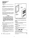
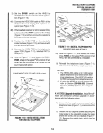
4.30 DDSS Console Connections
4.31
DDSS consoles must be located adjacent to
a digital or electronic telephone (preferably an
LCD model). DDSS consoles are connected to the
PDKU (viathe MDF) using standard twisted single-
pair or two-pair jacketed telephone cable (maxi-
mum 1000 feet, 303 M). The console uses only
circuit 8on the PDKU. To accommodate the DDSS
console connection, the instrument end of the
cable should be terminated in a modular station
connector block (RJ-11). Refer to Wiring Dia-
grams, Section 200-096-209, for wiring/intercon-
necting details, including cable length limitations.
CAUTION!
When installing the station cable, do not
run parallel to and within 3 feet of an AC
power line. AC power lines should be
crossed at right (90”) angles only. In par-
ticular, avoid running station wire pairs
neardevices thatgenerateelectricalnoise,
such as neon or fluorescent light fixtures.
4.32 DDSS Console Configuration.
The follow-
ing considerations should be made when installing
DDSS consoles:
l
A PDKU PCB is required to use the DDSS
console.
l
A maximum of four DDSS consoles are allowed
per system.
l
One PDKU circuit is required for each DDSS
console (always circuit 8).
l
Only one DDSS console may be connected to a
PDKU.
4.33 DDSS Programming Overview
Program 03
l
Code 64 identifies PDKU slots that support
DDSS consoles.
I
Program 28
l
Assigns DDSS console(s) to digital telephones.
7-11