


INSTALLATION-SYSTEM DESCRIPTION
SECTION 200-096-202
FEBRUARY1991
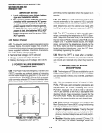
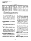
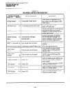
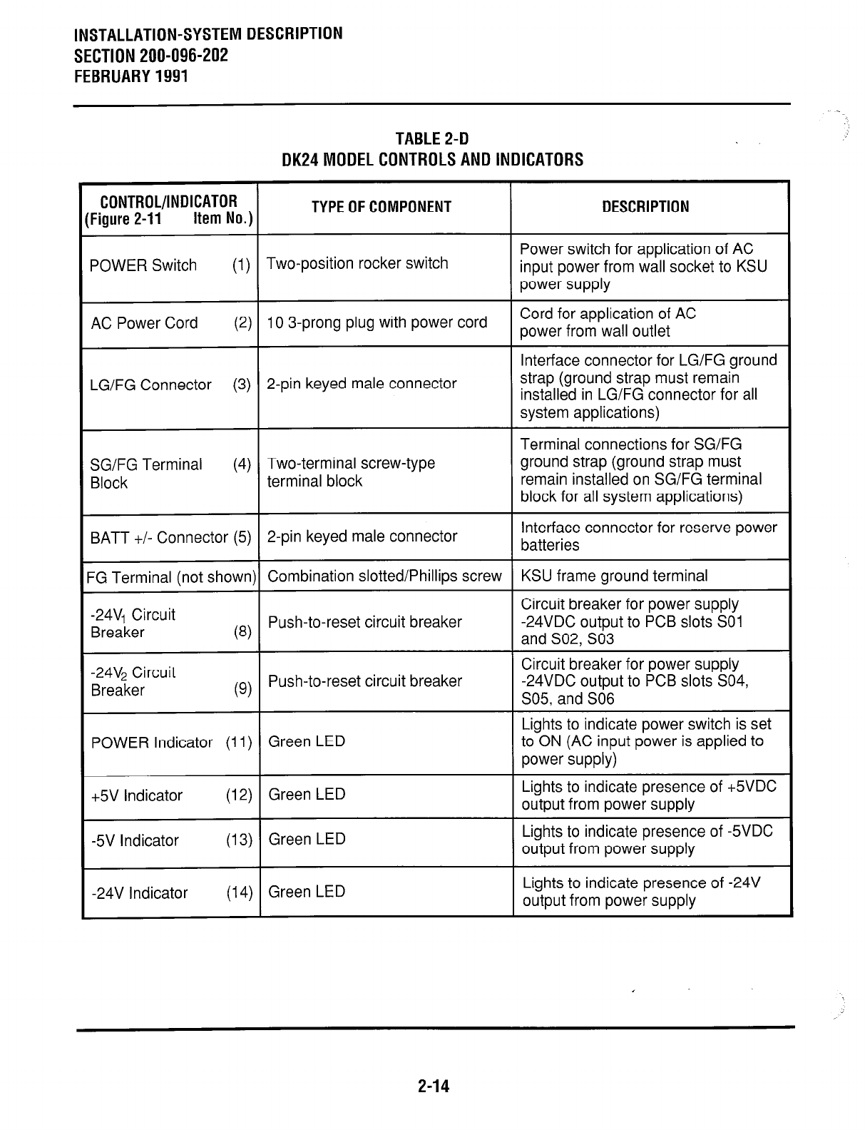
TABLE2-D
DK24MODELCONTROLSANDlNDlCATORS
CONTROL/INDICATOR
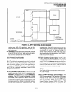
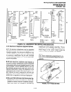
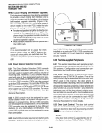
Figure 2-11
Item No.)
TYPE OF COMPONENT
POWER Switch
(I) Two-position rocker switch
DESCRIPTION
Power switch for application of AC
input power from wall socket to KSU
power supply
AC Power Cord (2) 10 3-prong plug with power cord
Cord for application of AC
power from wall outlet
Interface connector for LG/FG ground
LG/FG Connector (3) 2-pin keyed male connector
strap (ground strap must remain
installed in LG/FG connector for all
system applications)
SG/FG Terminal
(4) Two-terminal screw-type
Block
terminal block
Terminal connections for SG/FG
ground strap (ground strap must
remain installed on SG/FG terminal
block for all system applications)
BATT +/- Connector (5)
2-pin keyed male connector
Interface connector for reserve power
batteries
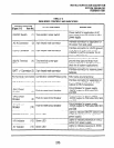
-G Terminal (not shown) Combination slotted/Phillips screw
KSU frame ground terminal
-24VI Circuit
Circuit breaker for power supply
Breaker
63)
Push-to-reset circuit breaker -24VDC output to PCB slots SO1
and S02, SO3
-24V2 Circuit
Breaker
(g) Push-to-reset circuit breaker
Circuit breaker for power supply
-24VDC output to PCB slots S04,
S05, and SO6
POWER Indicator (11) Green LED
Lights to indicate power switch is set
to ON (AC input power is applied to
power supply)
+5V Indicator
(12) Green LED
Lights to indicate presence of +5VDC
output from power supply
-5V Indicator (13) Green LED
Lights to indicate presence of -5VDC
output from power supply
-24V Indicator
(14) Green LED
Lights to indicate presence of -24V
output from power supply
2-14