


STRATA DK FAULT FINDING
SECTION 200-096-500
FEBRUARY 1991
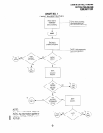
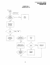
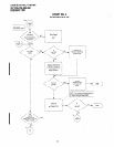
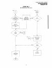
3.05 The flowcharts are sequentially arranged to
permit rapid fault localization within the system.
All
fault clearing must begin with the Fault Classifica-
tion Flowchart, which is arranged in the correct fault
locating sequence.
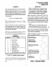
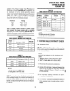
3.06 The following precautions must be observed
when handling PCBs:
DO
NOT:
l
Drop a PCB.
l
Stack one PCB on top of another.
l
Handle a PCB without discharging any static
electricity from your person by touching the
grounded cabinet.
0 Touch PCB contacts with your fingers.
IMPORTANT!
If the fault is not cleared by substituting a
PCB, the original PCB must be reinstalled
in the cabinet before trying another PCB.
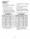
4 DEFECTIVE APPARATUS RETURNS
4.01 When adefective system apparatus is shipped
for repair, the apparatus must be packed in a
suitable container (the original box is highly recom-
mended), as follows:
c) Plastic bags for electronic telephones, KSU,
etc.
.
4.02 NEVER WRITE ON THE APPARATUS IT-
SELF! Describe the nature of the defect on an
information tag. Attach the tag to the front of the unit
with string (not wire) so the tag can remain attached
during the testing and repair process. Return tags
are available from Toshiba America Information
Systems, Inc., TSD Division.
4.03 If different and/or additional faults are created
in the system by substituting a PCB, tag and return
the substitute PCB as a defective unit.
5 FAULT IDENTIFICATION and
ELIMINATION PROCEDURES
5.01 The PCTU PCB may contain a “soft” fault due
to static electricity. If it is found defective during the
fault finding procedures, attempt to clear a soft fault
prior to returning the PCTU PCB for repair. The
correct procedure for this is to reinstall the PCTU,
perform the initialization procedure, and then re-
program the system as necessary to test for the
fault. If the fault returns after these procedures are
performed, tag the defective PCTU and return it for
repair.
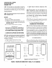
6 POWER SUPPLY
a) Paper container for the PCTU PCB.
b) Anti-static containers for all other PCBs.
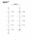
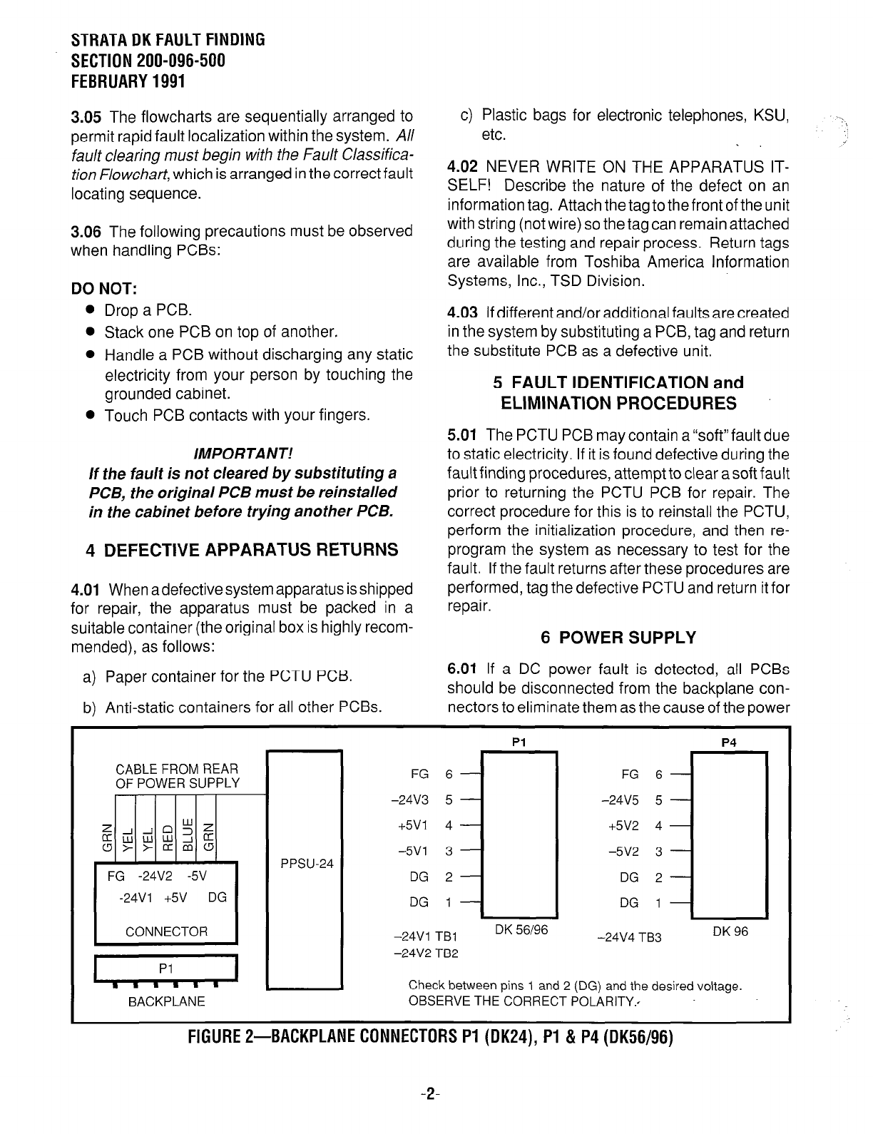
6.01 If a DC power fault is detected, all PCBs
should be disconnected from the backplane con-
nectars to eliminate them as the cause of the power
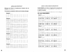
CABLE FROM REAR
OF POWER SUPPLY
wz
g$gi;g
FG -24V2 -5V
-24Vl +5V DG
CONNECTOR
BACKPLANE
FG 6
-24V3 5
+5VI 4
-5Vl 3
DG 2
DG 1
-24Vl TBl
-24V2 TB2
Pl P4
DK 56196
-24V4 TB3
DK 96
FG
-24V5
+5V2
-5V2
DG
DG
i-l
Check between pins 1 and 2 (DG) and the desired voltage.
OBSERVE THE CORRECT POLARITY..
FIGURE P-BACKPLANE CONNECTORS Pl
(DK24),
PI & P4 (DK56/96)
-2-