


STRATADK .
GENERALDESCRIPTION
DECEMBER1990
b
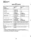
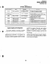
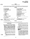
TABLEL
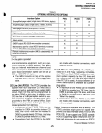
OPTIONALSUBASSEMBLIES
^
Subassembly
Host
Capacity
Function
EOCU
PEKU and PESU
1 for PEKU or PESU
that supports OCA
Provides OCA path for 8 circuits
on PEKU or 4 circuits on PESU.
CRCU
(4 or 8 circuits)
PCTU or PCTUS 1 per PCTlkystem
Provides DTMF receiver for DISA,
standard telephone circuits, and TIE lines.
IMDU
PIOU or PIOUS
1 per PlOWsystem
Provides remote maintenance
interface with built-in modem.
HHEU
HVSU
HVSI
DVSU
6500-series EKT/
1 OOO-series DKT
6500-series EKT
6500-series EKT
1 OOO-series DKT
1 per EKT/DKT
1 per EKT
1 per EKT
1 per DKT
Provides interface for headset and loud
ringing bell.
Provides interface for EKT to receive OCA.
Provides interface for EKT to receive OCA.
Provides interface for DKT to receive OCA.
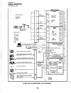
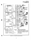
System Capacity and Configuration
This section provides an overview of system
configuration requirements and considerations.
port/CO line capacity. Generally, each optional
PCB, e.g. PEMU, PIOU, PIOUS, or PEPU,
installed in the cabinet occupies a slot that may
have been used to support eight station ports or
four CO lines.
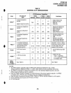
Table A I illustrates each system’s various
station/CO line capacities.
For
example, the
STRATA DK96 system can have 36 CO lines and
40 stations. Optional upgrades impact the station
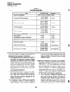
The number of station ports or CO lines pro-
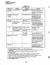
vided by each PCB is given in Table K. Tables L
and M list each type of subassembly and option-
al unit that can be installed.
-25-