INSTALLATION-KSU
SECTION 200-096-205
FEBRUARY1991
ii?
a
-
!
FG
2
-
?
-
CABLE FROM REAR
OF POWER SUPPLY
-24v2 -5v
BATTERY
CONNECTOR
-24V, +5V DG
CONNECTOR
VOLTAGE
LED’s
Pi
I
III III,
,
BACKPLANE
KSU (FRONT VIEW)
PPSU 24
Irr
0 \
. POWER
,POWER
SWITCH
’ CIRCUIT
\
BREAKER
MOUNTING
SCREWS ON
RIGHT SIDE
-\
TEST POINTS
CORD
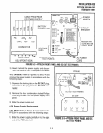
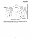
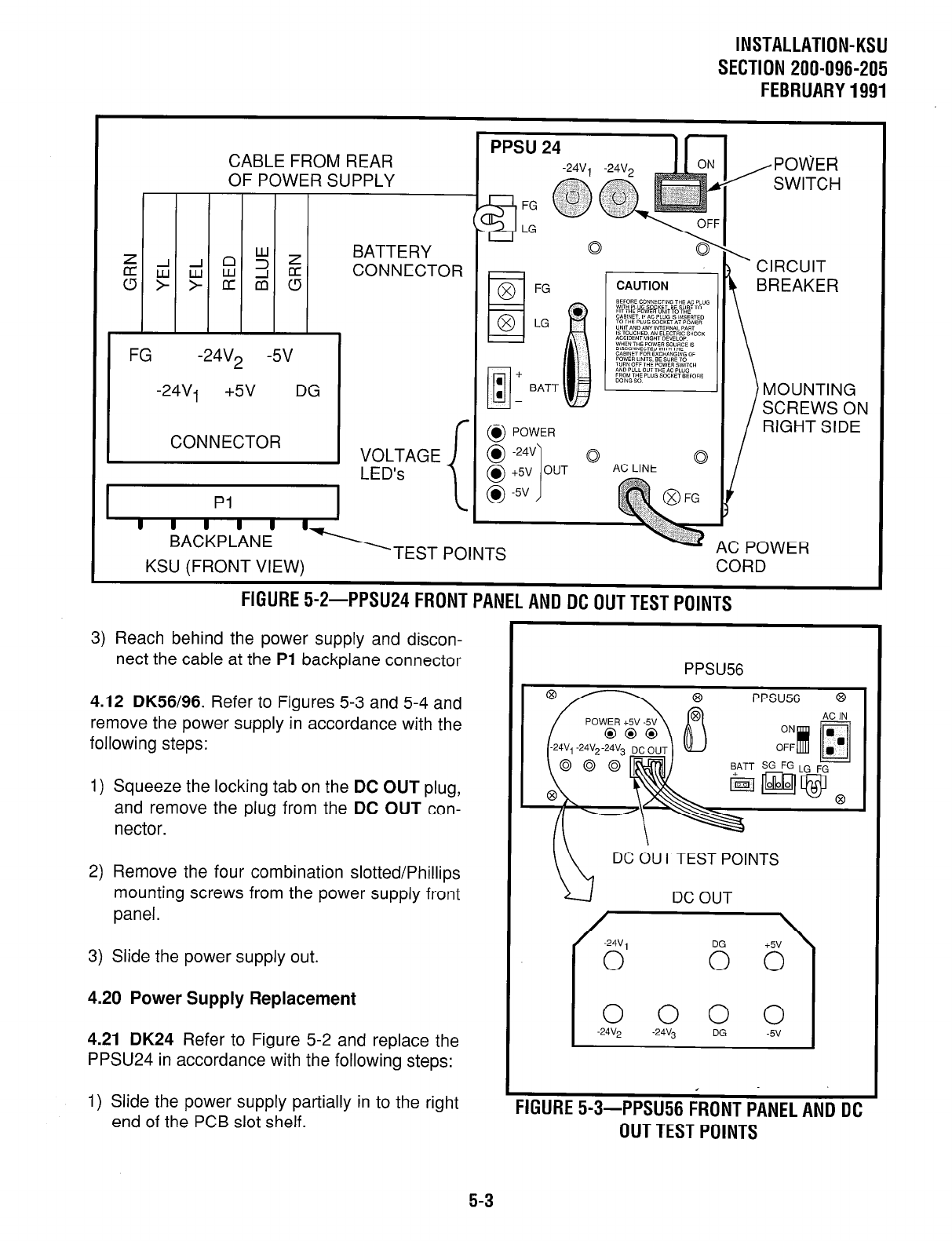
FlGURE5-2-PPSU24FRONTPANELANDDCOUTTESTPOlNTS
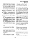
3) Reach behind the power supply and discon-
nect the cable at the
PI
backplane connector
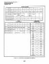
4.12 DK56/96. Refer to Figures 5-3 and 5-4 and
remove the power supply in accordance with the
following steps:
1) Squeeze the locking tab on the DC OUT plug,
and remove the plug from the DC OUT con-
nector.
2) Remove the four combination slotted/Phillips
mounting screws from the power supply front
panel.
3) Slide the power supply out.
4.20 Power Supply Replacement
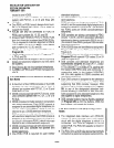
4.21 DK24 Refer to Figure 5-2 and replace the
PPSU24 in accordance with the following steps:
1) Slide the power supply partially in to the right
end of the PCB slot shelf.
PPSU56
PPSU.56 8
DC OUT TEST POINTS
DC OUT
I
0000
-24V2
-24v3 DG -5v
7
FIGURES-3-PP~U~~FRONTPANELANDDC
OUTTESTPOINTS
5-3


