


INSTALLATION-PCB
SECTION 200-096-206
FEBRUARY 1991
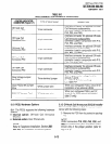
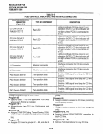
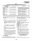
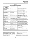
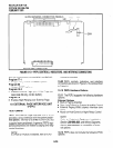
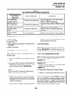
TABLE 6-F
PEMU CONTROLS, INDICATORS, AND INTERFACE CONNECTORS (continued)
I
CONTROL/INDICATOR
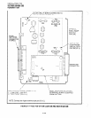
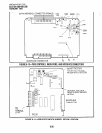
(Figure 6-9)
TYPE OF COMPONENT DESCRIPTION
GND/BAT Jumper
P402
2Wl4W Jumper
P103
Three-terminal jumper
Three-terminal jumper
M-lead origination for TIE line 4 (must
be in BAT position per FCC requirements)
Selects 2- or 4-wire configuration
for E & M TIE line circuit 1.
I
2Wl4W Jumper
P203
Three-terminal jumper
Selects 2- or 4-wire configuration
for E & M TIE line circuit 2.
I
2W/4W Jumper
P303
I
Three-terminal jumper
Selects 2- or 4-wire configuration
for E & M TIE line circuit 3.
I
2Wl4W Jumper
P403
I
Three-terminal jumper
Selects 2- or 4-wire configuration
for E & M TIE line circuit 4.
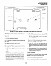
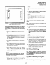
8.21 Install the PEMU in accordance with the fol-
lowing steps:
1) Remove the PCB from its protective packag-
ing.
2) Determine if the E & M TIE lines will be config-
ured as 2- or 4-wire. Set
2W/4W
switches
PI 03,
P203, P303,
and P403 to the appropriate po-
sitions.
3) Set the
FG
jumper P3 to the 2-3 position.
4)
Set all
GNDlBAT
jumpers to the
BAT
position
for connection to the telephone network.
NOTE:
The GND position is used to connect PEMU
circuits back-to-back on premises only, 1000
feet maximum (E & M lead wires must be
crossed).
5) Insert the PEMU into the appropriate slot (refer
to Paragraph 2.21) and apply firm, even pres-
sure to ensure proper mating of connectors.
6) After installing the PEMU, gently pull the PCB
outward. If the connectors are properly mated,
a slight resistance will be felt.
8.30 PEMU Wiring
8.31 In Section 200-096-209, refer to PEMU (2W
or 4W) wiring diagram for wiring/interconnecting
details, and to secondary protector diagram for
secondary protector information.
I
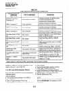
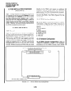
8.40 PEMU Programming Overview
8.41
The following parameters may be specified,
through programming, for the PEMU:
Program 03
l
Specify code 13 for applicable PCB slots where
each PEMU is installed.
Program 1 O-l
l
Allows or denies two-CO Line Conference.
Program 15
l
Assigns tandem connections to TIE lines.
Program 17
l
Assigns Page/Handsfree Answerback.
NOTE:
When a PEMU is installed in a system, it
automatically assumes the next consecutive
CO line and station port numbers. If the sys-
tem is equipped with a PCTU(1 or Z), the
PEMU assumes four CO line and four station
port numbers. However, with a PCTUSI, on/y
16 station ports will be available for stations
connected to a PEKU, PESU, or PSTU PCB.
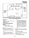
9 OPTION INTERFACE UNIT
(PIOU AND PIOUS)
9.00 General
9.01
The Option Interface Unit (PIOU or PIOUS)
6-19