


INSTALLATION-PCB
SECTION 200-096-206
FEBRUARY 1991
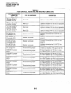
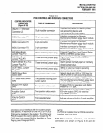
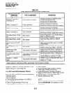
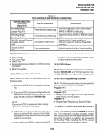
TABLE 6-l
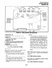
PEPU CONTROLS AND INTERFACE CONNECTORS
.
CONTROL/INDICATOR/
CONNECTOR
(Figure 6-13)
. -
M/B Make/Break
Jumper Plug PI0
TYPE OF COMPONENT DESCRIPTION
Three-terminal jumper plug
External Page/Door Lock Control Relay
MAKE or BREAK jumper plug.
I
M/B Make/Break
Jumper Plug PI 1
Three-terminal jumper plug
Night/Hold Relay MAKE or BREAK jumper
plug.
Two-position slide switch
Selects built-in 3-watt amplifier or
600-ohm output for External Page/BGM
operation.
I
Trim potentiometer
Adjusts volume of built-in 3-watt amplifier.
l
Alarm Sensor
l
Four-zone Page
l
SMDR Port
l
Remote Maintenance Modem or ASCII terminal
Connector
l
IMDU Connection
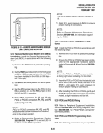
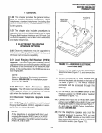
10.20 PEPU Installation Procedure
10.21 Install the PEPU in accordance with the
following steps:
1) Remove the PCB from its protective packag-
ing.
2) Ensure the PEPU has been configured for the
appropriate hardware options (refer to Para-
graph
10.10
and Section 200-096-208).
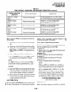
NOTE:
Ensure the PEP& component side is facing
right when installing it in the KSU.
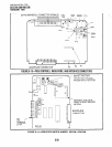
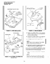
3) insert the PEPU into the last slot (slot 06 of
DK24, slot 08for DK56, and slot 14for DK96),
and apply firm, even pressure to ensure proper
mating of connectors,
4
.) After installing the PEPU, gently pull the PCB
6-25
outward. If the connectors are properly mated,
a slight resistance will be felt.
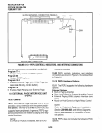
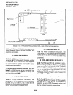
10.30 PEPU Wiring
10.31
Refer to Peripheral Equipment Installation,
Section 200-096-208; and Wiring Diagrams, Sec-
tion 200-096-209, forwiring/interconnecting details.
10.40 PEPU Programming Overview
10.41
The following parameters may be specified,
through programming, for the PEPU:
Program 77-1
l
Assigns relay control options.
Program 1 O-2
l
Assigns External Page to All Call Page (access
l
Enables Night Ringing over External Page.
code 39 only, not AC button).
Program 78
11 INSTALLATION-PCB FOR RELEASE 3
11
.Ol The following contains
Release
3 informa-
tion. This information includes complete installa-
tion instructions for the new digital telephone inter-
face PCB, the PDKU. In addition, the instructions
for the other PCBs, including the PCTU, are up-
dated to reflect the new software release.